M1series_ServiceManual_e.pdf - 第57页
4 Electrical Section 4-5 Electrodes on Feeder / Feeder Bank When electrodes on the feeder bank and the tape feeder get dirty, clean them as follows: Clean them very lightly to just get ri d of the dust with dry cotton sw…
4 Electrical Section
4-4
Control Board
Handling Control Board
Note the followings when handling PC boards.
z Do not touch control boards by wet hands.
z Do not handle control boards where there are metal chips around.
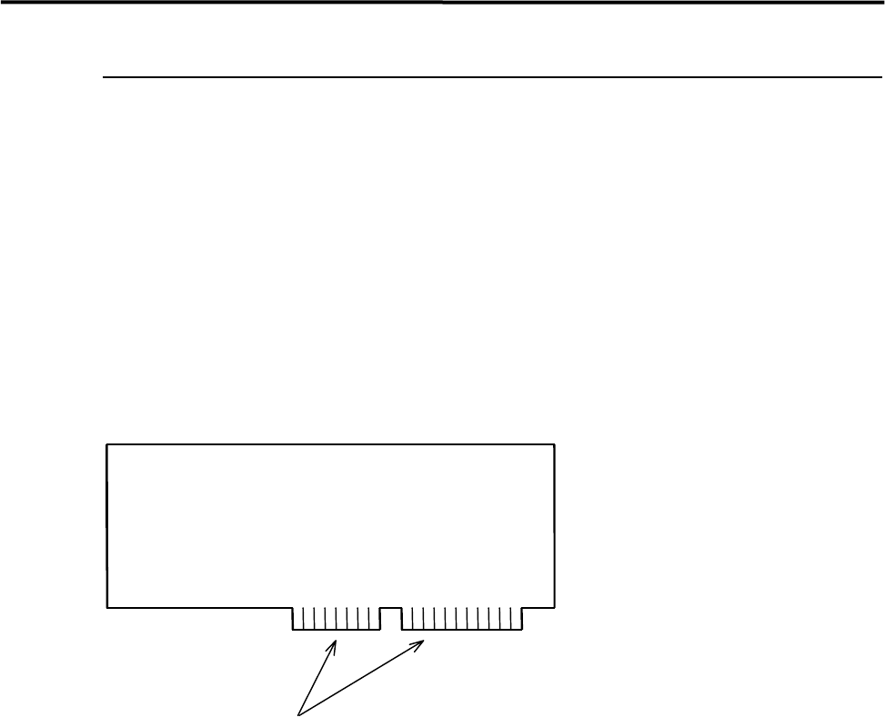
z To handle control boards in the control rack, never touch the connecting portion where gold is plated. If
the connecting portion is covered with dust, the machine doesn't work properly. Clean with alcohol.
Gold Plating
4 Electrical Section
4-5
Electrodes on Feeder / Feeder Bank
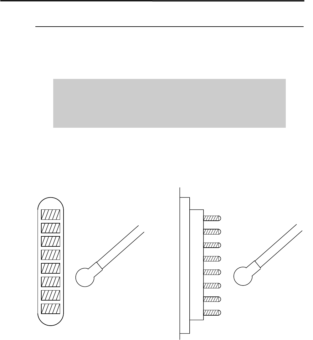
When electrodes on the feeder bank and the tape feeder get dirty, clean them as follows:
Clean them very lightly to just get rid of the dust with dry cotton swab or nonwoven fabric. Check the pins
for deformation. If you find a bent pin, do not use the feeder as it is. It may result in a flaw on electrodes.
Do not use alcohol, water base detergents and organic solvent, such as
thinner, benzene and acetone.
Do not use sandpaper and tools with sharp blade or edge, such as a knife and
a screwdriver.
NOTE: If they get stubborn stains, try not to get rid of them forcedly. Please contact us.
Cotton swab
Pin Electrodes on feederElectrodes on feeder bank
Cotton swab
4 Electrical Section
4-6
Adjustment of Board Detection Sensors
■ Sensors
z LG0-M90H3-00X PHOTO SENSOR EX-22A (SUNX)
・ Entrance Sensor
・ Exit Sensor
・ Exit Buffer Arrival Sensor
z LG0-M90H1-00X PHOTO SENSOR AMP. PS2-61 (KEYENCE)
LG0-M90H2-00X PHOTO SENSOR HEAD PS-49 (KEYENCE)
・ Board Arrival Sensor
・ Buffer Board Arrival Sensor
■ Adjustment
z LG0-M90H3-00X PHOTO SENSOR
① Place a production board on the conveyor.
② Turn the Sensitivity Adjuster fully counterclockwise to the sensitivity minimum position. (The
adjuster turns 3/4 rotation overall. If it is turned clockwise, the sensitivity increases, if turned
counterclockwise, the sensitivity decreases.)
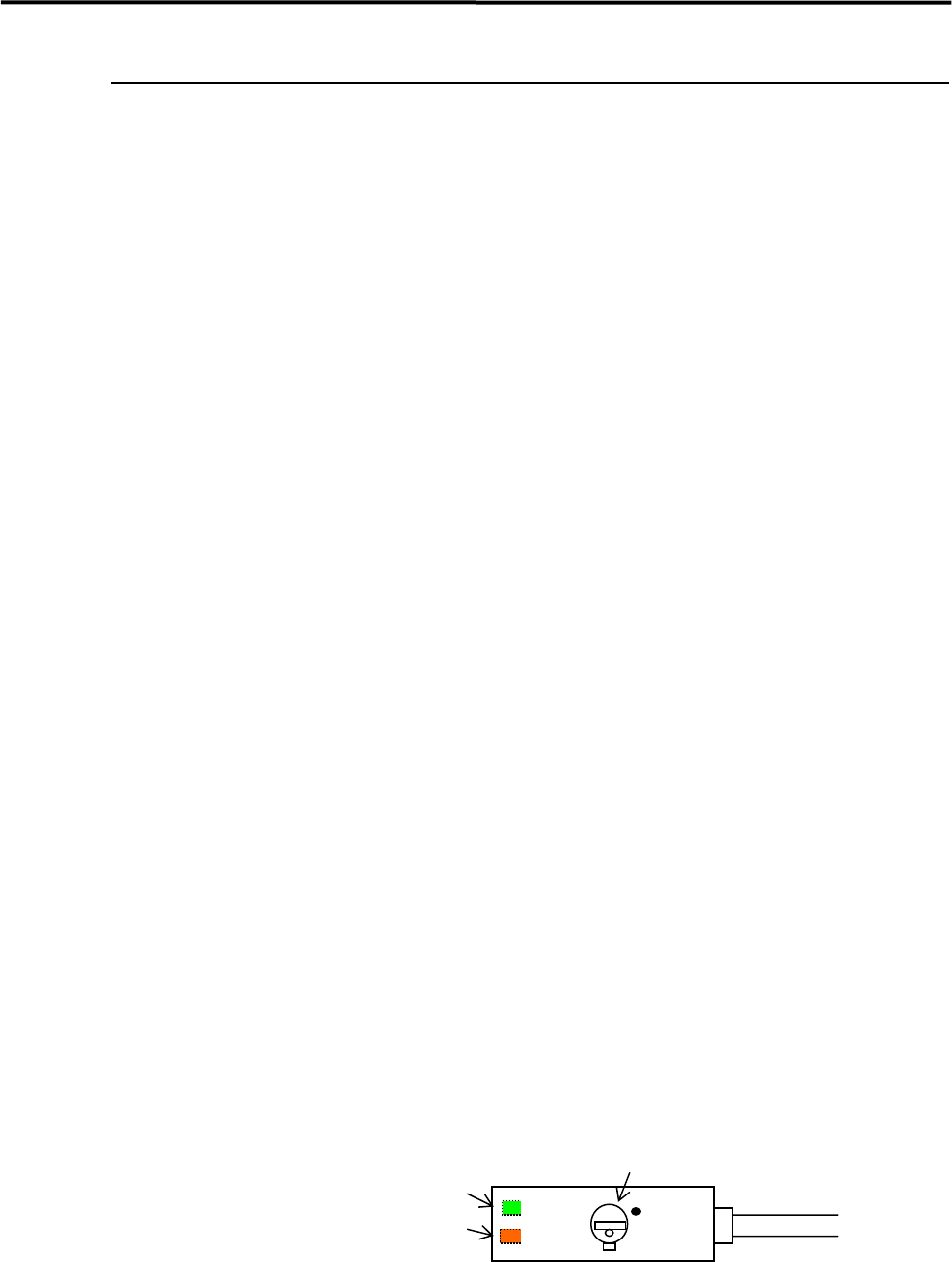
③ Turn the Sensitivity Adjuster clockwise slowly and confirm the point “A” where the Orange LED
lights up.
④ Remove the board and continue to turn Sensitivity Adjuster clockwise and confirm the point “B”
where the Orange LED lights up. (If the sensor does not light up, just turn the adjuster clockwise to the
end.)
⑤ Turn the Sensitivity Adjuster to the center of “A” and “B”. Determine the point as a detecting point.
⑥ Put back the board on the conveyor. Be sure that the Orange LED and Green LED light up at the same
time. When you remove the board, only the Green LED should light up.
NOTE: If your machine is equipped with the CE safety conveyor cover, make sure to stick the black rubber sheet
(LG0-M9AA1-00 GOM) on the bottom surface of the cover to prevent mis-detection.
Operation Indicator (Orange LED)
(Indicators are located on the back.)
Stability Indicator (Green LED)
Sensitivity Adjuster
MAX