M1series_ServiceManual_e.pdf - 第60页
4 Electrical Section 4-8 Cautions about overall electrical items Once rats enter indoors or buildings, t hey easily get into machi nes. They may tear wirings and leave excrement that can cause se rious dam age to machine…
4 Electrical Section
4-7
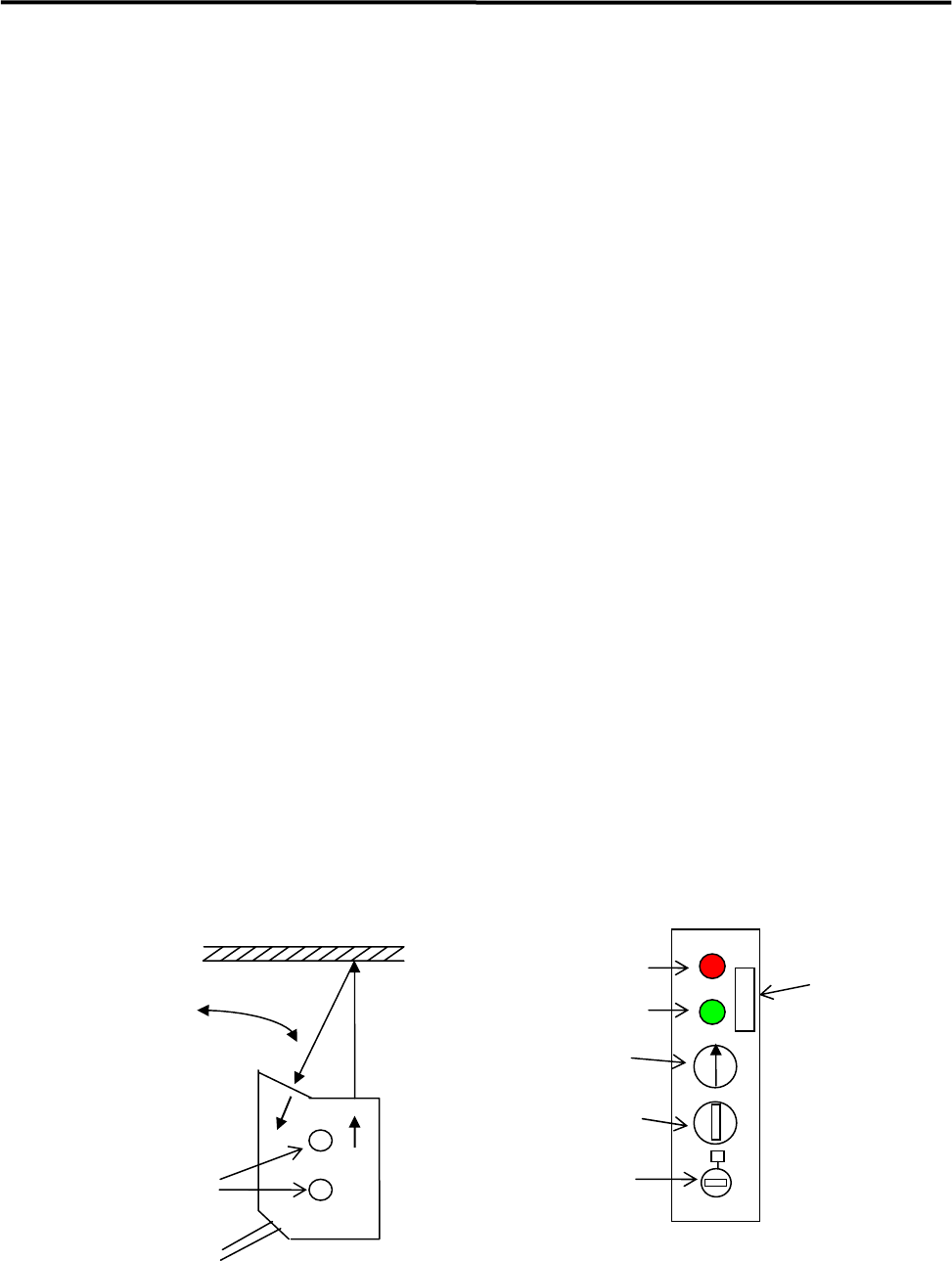
z LG0-M90H1-00X PHOTO SENSOR AMP.
LG0-M90H2-00X PHOTO SENSOR HEAD
① Place a production board on the conveyor.
② Find the optimum angle of the Sensor Head.
(1) Loosen two screws of the Sensor Head a little.
(2) Turn the Sensitivity Adjuster fully counterclockwise to the sensitivity minimum position.
(The adjuster turns 3 rotations overall. If it is turned clockwise, the sensitivity increases, if
turned counterclockwise, the sensitivity decreases. The adjuster clicks when it reaches the end
position.)
(3) Turn the Sensitivity Adjuster one rotation clockwise.
(4) Have the sensor detect the board and adjust the angle of the Sensor Head so that the sensor
becomes “Stable operating state” (Red and Green LEDs light up at the same time.). Decide the
angle at the midpoint in the range of the Sensor's “Stable operating state”. Then tighten the
screws.
③ Turn the Sensitivity Adjuster fully counterclockwise to the sensitivity minimum position.
④ Have the sensor detect the board and turn the Sensitivity Adjuster clockwise slowly and confirm the
point “C” where the Red LED lights up.
⑤ Turn the Sensitivity Adjuster fully clockwise to the sensitivity maximum position.
⑥ Remove the board and move the machine's head assembly over the sensor in all directions. Check if
the Red LED lights up. If the Red LED lights up, turn the Sensitivity Adjuster counterclockwise and
find the point “D” where the Red LED goes out. If the Red LED does not light up, turn the Sensitivity
Adjuster fully clockwise.
⑦ Turn the Sensitivity Adjuster to the center of “C” and “D”. Determine the point as a detecting point.
⑧ Put back the board on the conveyor. Be sure that the Red and Green LEDs light up. If you remove the
board, both LEDs should go out.
Adjust the angle.
Mounting Screws
Stable Operation Indicator
(
Green LED
)
Operating Indicator
(Red LED)
Board
Operation Mode Switch
(
Fixed at 1
)
Timer Setting Trimmer
(No adjustment needed)
Sensitivity Adjuster
(3-rotation type)
Alarm Switch
(OFF)
Sensor Head Sensor Amplifier
4 Electrical Section
4-8
Cautions about overall electrical items
Once rats enter indoors or buildings, they easily get into machines. They may tear wirings and leave
excrement that can cause serious damage to machines.
If rats tear wirings, it may cause short circuits. And it could cause a serious problem to machines.
If rats leave excrement over printed circuits boards or bared cables, it will be carbonized and may cause
fire.
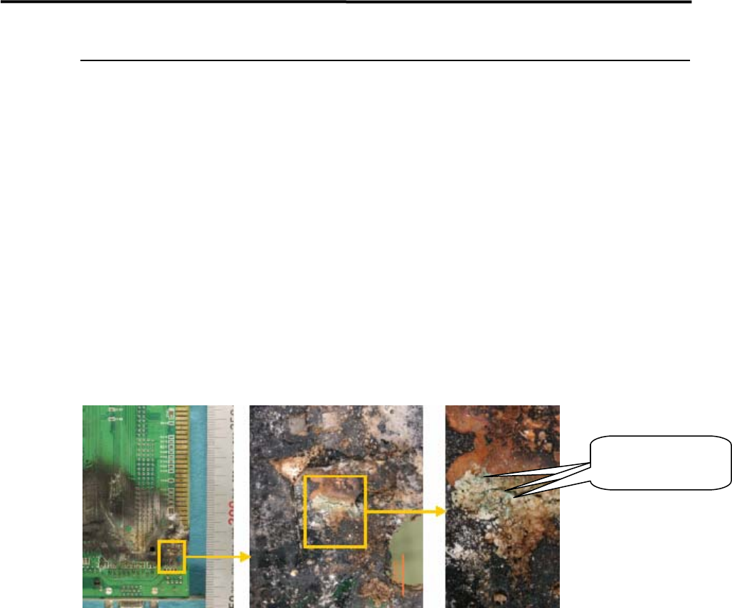
REFERENCE:
Below is an example we had fire from a board. (See the pictures below.)
You can see blue-green attached material on the burnt location.
When copper burns, Cuo (copper oxide II) is black and Cu2O (copper oxide I) is red. According to the
blue-green color, the attached material can be considered Copper hydroxide. By this fact, we suppose water
existed on the burnt location.
Blue-green
attachments
COUNTERMEASURE:
1.Keep the room clean, neat and organized.
2.Lock up the room with no openings.
If once rats came in;
3.Sprinkle rat repellent.
4.Catch rats with adhesive sheets. (Emergency countermeasure)
5.Hire an rat exterminator.
To prevent damage caused by rats, it is important to keep rats-free environment.
If already rats are in your space, exterminate them by using rat repellent or other ways as mentioned above.

5 Materials
5-1
5
Materials