00196433-02_AI_Vakuumpumpe_X-Serie_70XDE+EN.pdf - 第75页
Assembly instructions: Vacuum pump for SIPLACE X-series 04/2009 Edition 75 2.7 T echnical information about the vacuum pump 2.7.1 Special features of the vacuum pump The vacuum pump is switched on and off togeth er with …

Assembly instructions: Vacuum pump for SIPLACE X-series
04/2009 Edition
74
2.6 Pneumatic system and vacuum supply
2
It is not possible to convert placement machines with serial numbers earlier than B079. 2
2
2
2
The compressed air must not be switched on during the conversion otherwise there is a potential
risk of damaging the placement head. 2
2
The conversion to vacuum pump operation of a placement machine with two C&P20 heads is il-
lustrated below. 2
2
2
No more than two CP20 A placement heads may be connected to a vacuum pump.
For the requirements (which depend on the machine configuration), see Chapter 2.7.2. 2
2
2
2
If a TwinHead or CPP placement head is used, the air supply, the gantry distributor and the cable
and hose carrier for the gantry concerned must NOT be converted as this would stop the Twin-
Head or CPP working. 2
2
2
2
The machine and thus the vacuum pump should not be switched off and on again in quick suc-
cession as this can greatly shorten the service
life of the pump.
Switching the vacuum pump off and on for longer production stoppages, for example, is monitored
by the placement mach
ine. 2
2
Assembly instructions: Vacuum pump for SIPLACE X-series
04/2009 Edition
75
2.7 Technical information about the vacuum pump
2.7.1 Special features of the vacuum pump
The vacuum pump is switched on and off together with the placement machine. The software pro-
vides a follow-up time of 6 minutes to avoid a overheating
of the motor because of start-up peak.2
2.7.2 Special features of the C&P 20 placement head
A vacuum pump, X-series (item no.: 00119787-xx) can supply one or two C&P20 heads. 2
When the vacuum pump option is retrofitted with the C&P20
head, the Venturi vacuum generator
(“Vacuum unit, holding circuit C&P20“) is replaced with the “Orifice ring, complete, C&P20”
(03046348-). Only the holding circuit is supplied directly by the vacuum pump.
In the pick-up or placement position, the pressure contr
ol valve and the return cylinder neverthe-
less continue to be supplied with co
mpressed air. 2
The placement machine's “vacuum consumption” is only depen
dent on the number of placement
heads and the nozzle sizes. The more C&P20 heads are connected to the vacuum pump, the
more the vacuum drops off at the nozzles. 2
When the placement process starts, the vacuum increases with every component that is picked
up. Soon there will be an average
vacuum value calculated from those nozzles that are closed
(with picked-up components) and those that are open (components set down). 2
On an X4, once the placement process is running, 2 out o
f 4 heads are always closed with com-
ponents. 2
2.7.3 Special features of the C&P 6/12 placement head
A vacuum pump can supply up to four C&P6/12 heads. 2
The vacuum pump must only be connected to one m
achine, however. There must be no place-
ment heads from a second machine connected to the vacuum pump. 2
On the C&P6/12, a modified vacuum generator is integrated
into the head. In this way, the pick-
up circuit is supplied by Venturi nozzles and the holding circuit by the vacuum pump. 2
When the placement head is in the waiting position, th
e star is between two star positions (half-
cycle). 2
In this intermediate position, the holding and pick-up
circuits are connected to one another via the
polished disk. If a placement machine is switched off in this park position, the vacuum will drop.
This will affect the heads of all machines that are connected if there are no stop valves fitted. 2
It is only when the nozzles of all switched-off placeme
nt machines are perpendicular that there is
no interaction between the machines connected by the vacuum pump, even without (closed) stop
valves. 2
Assembly instructions: Vacuum pump for SIPLACE X-series
04/2009 Edition
76
2.8 Conversion
: Undock the component trolley at location 2 and 4.
: Switch the placement system off at the main switch and disconnect
from the power supply.
2
Before starting ANY work, 2
shut down the operating system correctly, then switch the machine OFF at th
e main power switch
and disconnect from the main power supply. In addition, the compressed air supply must be
switched off at the compressed air unit's main valve in the machine base and vented by actuating
the needle valve on the compressed air unit. 2
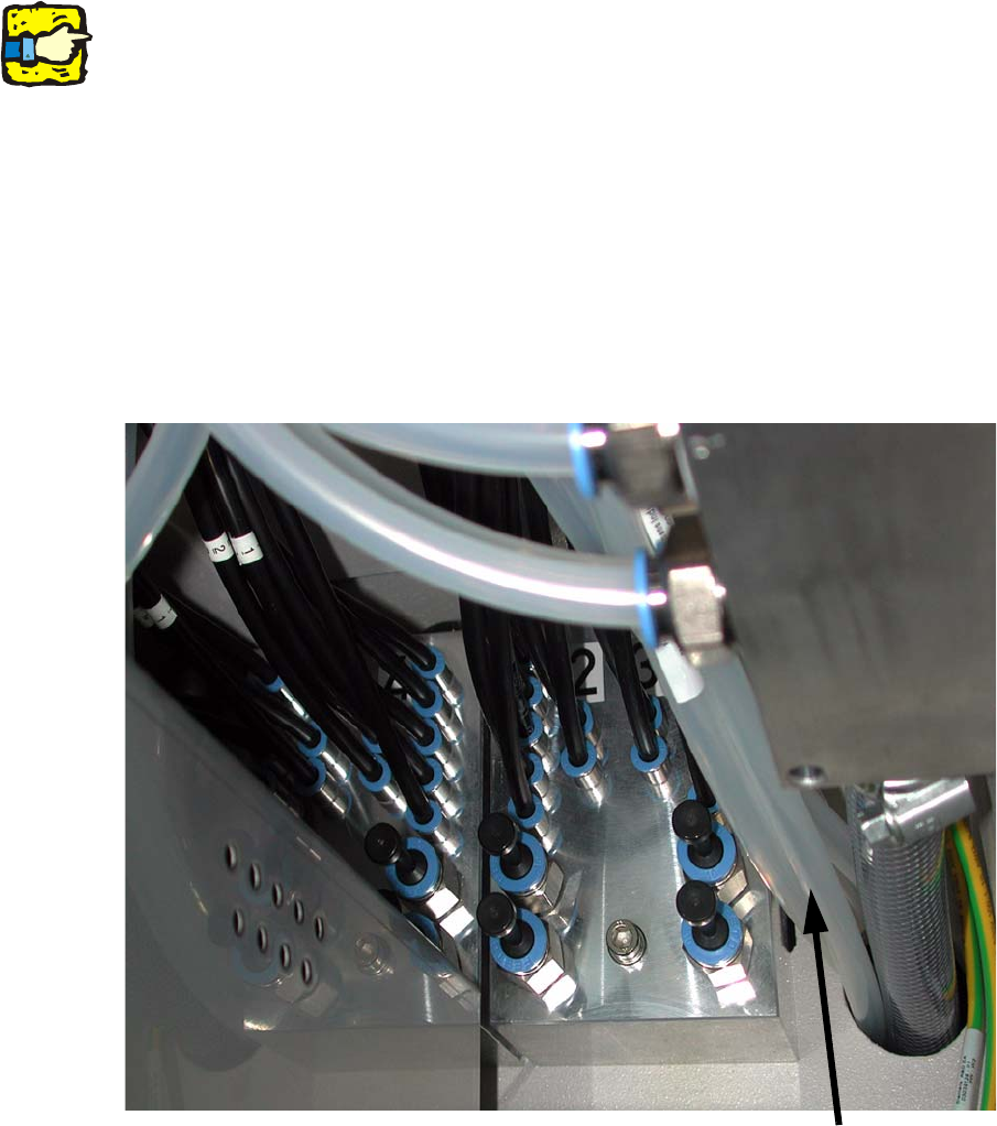
2.8.1 Connecting the gantry distributor
: Open the door to the compressed air supply
(where you will find the connections for gantry 3 and 4)
Air connections for machines with serial number D-001
Vacuum hoses
2