00196433-02_AI_Vakuumpumpe_X-Serie_70XDE+EN.pdf - 第80页
Assembly instructions: Vacuum pump for SIPLACE X-se ries 04/2009 Edition 80 : Pull the hoses down so you can see the labeling. Fig. 2.8 - 4 Labeling on the hoses (in this case for gantr y 3+4) Fig. 2.8 - 5 Converted pneu…
Assembly instructions: Vacuum pump for SIPLACE X-series
04/2009 Edition
79
Remove the following blanking plugs according to the gantry configuration: 2
2
A gantry with TwinHead and CPP head cannot be converted. Leave the blanking plugs for the rel-
evant gantry in the distributor. 2
2
Machines with serial number B-079 2
– X2: Plug for gantry 1 (power supply side)
and gantry 3 (air pneumatic side)
– X3: Plug for gantry 1 + 2 (power supply side) and gantry 3 (air pneumatic side)
– X4: Plug for gantry 1 + 2 (power supply side) and gantry 3 + 4 (air pneumatic side)
Ma
chines
with serial number D-001 (pneumatic side, gantry 1 - 4) 2
: On
ly set up those gantries that you want to operate with the vacuum.
2
If you convert the wrong gantry, there is a risk of damaging the placement head. 2
2
2
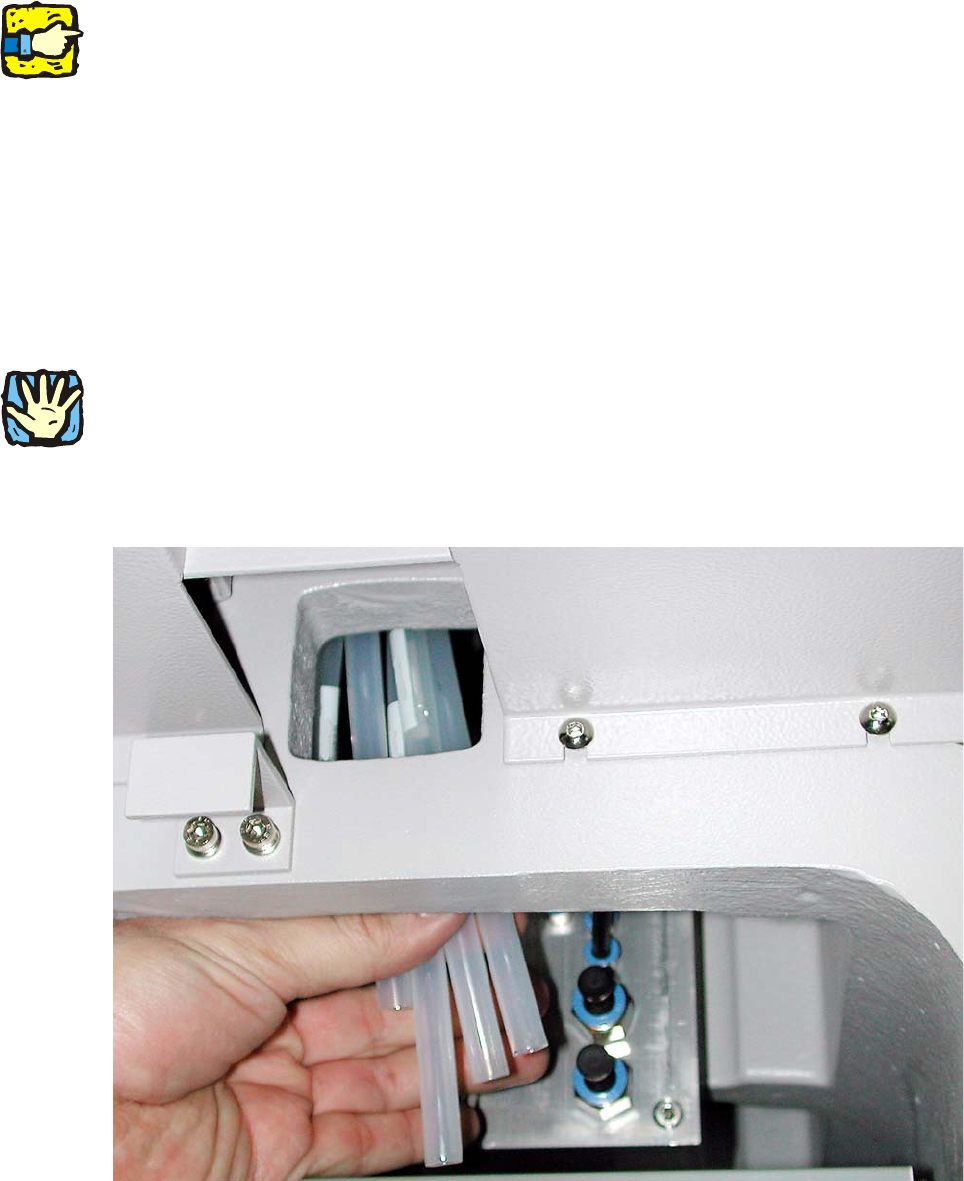
: Press the blue rings (see Fig. 2.8 - 2) down axially and remove the relevant blanking plugs.
Fig. 2.8 - 3 Factory-fitted hoses (in this case for gantry 1+2)
Assembly instructions: Vacuum pump for SIPLACE X-series
04/2009 Edition
80
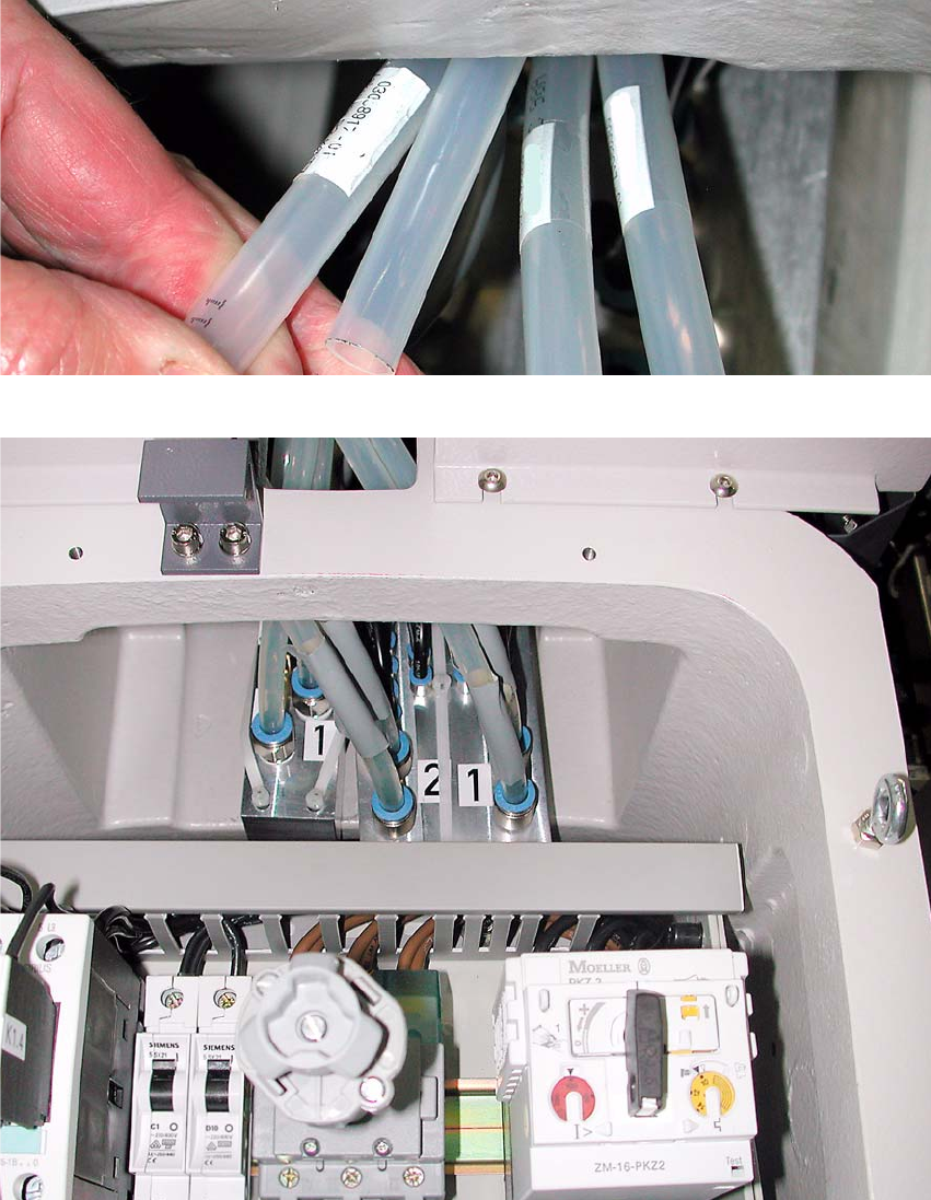
: Pull the hoses down so you can see the labeling.
Fig. 2.8 - 4 Labeling on the hoses (in this case for gantry 3+4)
Fig. 2.8 - 5 Converted pneumatic distributor for gantry 1+2 (opposite side)
: Attach the hoses to the gantry distributor – according to the labeling and machine configuration
(for both gantry 1+2 and gantry 3+4).
Assembly instructions: Vacuum pump for SIPLACE X-series
04/2009 Edition
81
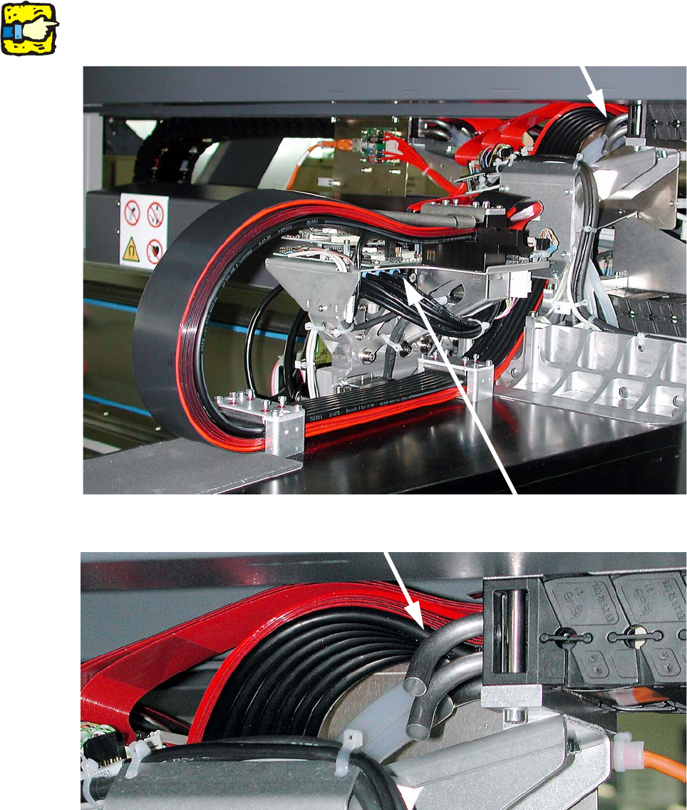
2.8.2 Gantries
2
The conversion of a distributor for placement heads to vacuum pump operation is illustrated be-
low. 2
2
Fig. 2.8 - 6 Vacuum connection points on gantry 1+3 (initial state)
2
Fig. 2.8 - 7 Hose connection, cable and hose carrier for gantry 1+3