00196433-02_AI_Vakuumpumpe_X-Serie_70XDE+EN.pdf - 第88页
Assembly instructions: Vacuum pump for SIPLACE X-se ries 04/2009 Edition 88 : Cut the two colored hose s to length: 490 mm. : Attach the hoses to the “Duo hose connection” and the connecto r on the cable and hose carrier…
Assembly instructions: Vacuum pump for SIPLACE X-series
04/2009 Edition
87
: Fix the hoses (two-color) to the “Duo hose connection”.
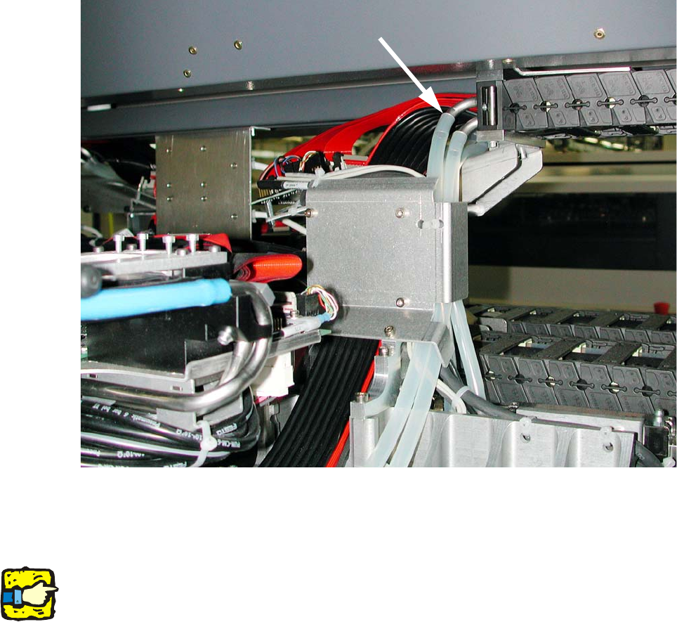
Fig. 2.8 - 15 Running the vacuum hose, gantry 1+3
: Run the hoses (transparent) under the guide plate and up
(see Fig. 2.8 - 15).
2
As there are different variants of the gantry cable and hose carrier, there may be differences here.
If necessary, use cable ties to fix the hoses to the ex
isting cables (see Fig. 2.8 - 8).
Be careful NOT to reduce the ho
se cross-sections with the cable ties. 2
2
2
2
2
2
2
2
2
Assembly instructions: Vacuum pump for SIPLACE X-series
04/2009 Edition
88
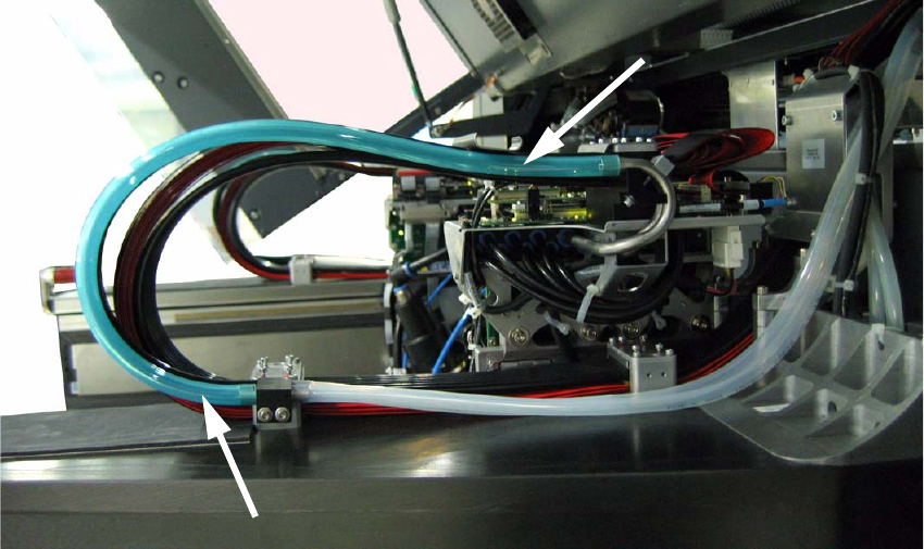
: Cut the two colored hoses to length: 490 mm.
: Attach the hoses to the “Duo hose connection” and the connector on the cable and hose carrier
(see F
ig. 2.8 - 15 and Fig. 2.8 - 16).
Fig. 2.8 - 16 Running the vacuum hose, gantry 2+4
2
: Check that the vacuum hoses are run correctly on the gantry. They must run parallel to the ca-
ble and hose carrier at a distance from it, otherwise there is a risk that the cable and hose car-
rier or the hoses themselves will be damaged.
2
2
2
2
Assembly instructions: Vacuum pump for SIPLACE X-series
04/2009 Edition
89
2.8.3 Converting the pneumatic unit
2
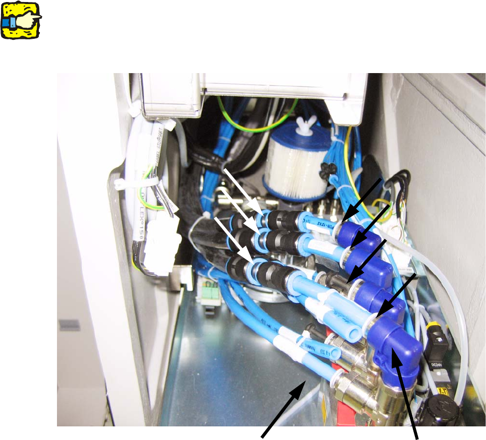
There are currently 3 different versions of the pneumatic unit in the X-series. This section
describes the basic conversion of the pneumatic unit. Please note that your specific pneumatic
unit may look different.
Gantry 1
Gantry 4
Gantry 3
Gantry 2
Reducers
Placement/pick-up circuit
or return cylinder
Holding
circuit
2
Fig. 2.8 - 17 Pneumatic unit with pressure connections (connections in the initial state). As there are different versions
of the pneumatic unit, there may be minor visual differences in your pneumatic unit.
2
2
2
2
2
2