00196433-02_AI_Vakuumpumpe_X-Serie_70XDE+EN.pdf - 第89页
Assembly instructions: Vacuum pump for SIPLACE X-series 04/2009 Edition 89 2.8.3 Converting th e pneumatic unit 2 There are curren tly 3 diff erent versions of the pneumatic u nit in the X-series. Th is section describes…
Assembly instructions: Vacuum pump for SIPLACE X-series
04/2009 Edition
88
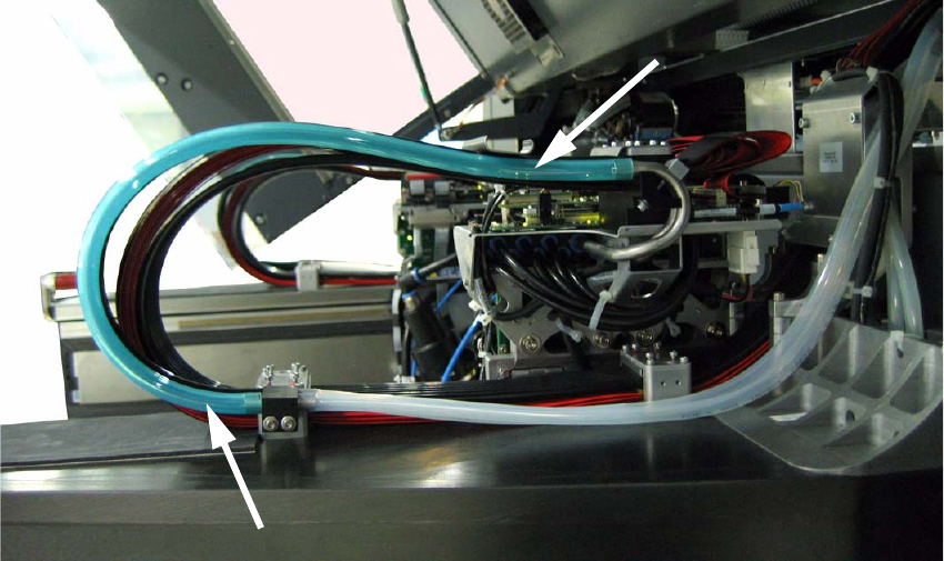
: Cut the two colored hoses to length: 490 mm.
: Attach the hoses to the “Duo hose connection” and the connector on the cable and hose carrier
(see F
ig. 2.8 - 15 and Fig. 2.8 - 16).
Fig. 2.8 - 16 Running the vacuum hose, gantry 2+4
2
: Check that the vacuum hoses are run correctly on the gantry. They must run parallel to the ca-
ble and hose carrier at a distance from it, otherwise there is a risk that the cable and hose car-
rier or the hoses themselves will be damaged.
2
2
2
2
Assembly instructions: Vacuum pump for SIPLACE X-series
04/2009 Edition
89
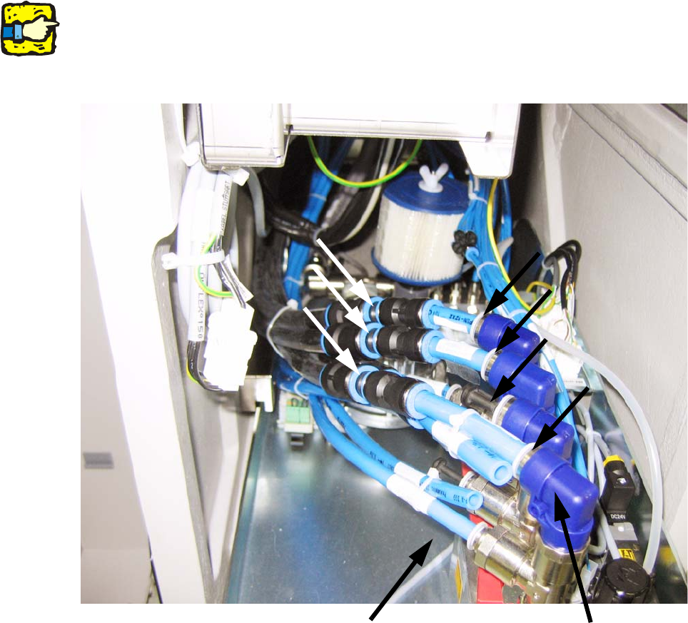
2.8.3 Converting the pneumatic unit
2
There are currently 3 different versions of the pneumatic unit in the X-series. This section
describes the basic conversion of the pneumatic unit. Please note that your specific pneumatic
unit may look different.
Gantry 1
Gantry 4
Gantry 3
Gantry 2
Reducers
Placement/pick-up circuit
or return cylinder
Holding
circuit
2
Fig. 2.8 - 17 Pneumatic unit with pressure connections (connections in the initial state). As there are different versions
of the pneumatic unit, there may be minor visual differences in your pneumatic unit.
2
2
2
2
2
2

Assembly instructions: Vacuum pump for SIPLACE X-series
04/2009 Edition
90
2
Gantries with TwinHead or CPP heads cannot be converted. Leave the gantry hoses for the rele-
vant gantry connected to the pneumatic unit.
2
: Pull out the pneumatic unit.
2
As we can see here, this placement machine is operated with 3 gantries (on one compressed air
connection there is a blanking plug, rather than a pressure hose).
2
If you do ever want to restore it to operation with compressed air, you must first connect the
hoses as they are labeled (see Fig. 2.8 - 17).
2
2
Only the holding circuit for the placement heads is converted. The connections for the holding cir-
cuit are those at the top of the pneumatic distributor. 2
The bottom connections are for the placement/pick-up circuit or
for the return cylinder. They must
not be changed. 2
2
2
2
2
2
2
2
2
2
2
2
2
2
2
2
2
2
2