SM_SXDX12_intern_03-2017_en.pdf - 第26页
Service Work Y-guide carriage / Y-loose bearing Replace Replacing the storage Cart 26 Service Manual (Internal) SIPLACE SX1/SX2/DX1/DX2 Unplug the cab le trai ling. See also Chapter 3.3.12 SX1_2 Ser vice Manual Y-trailin…
Service Work
Prepare the guide carriage Y-guide carriage / Y-loose bearing Replace
Service Manual (Internal) SIPLACE SX1/SX2/DX1/DX2 25
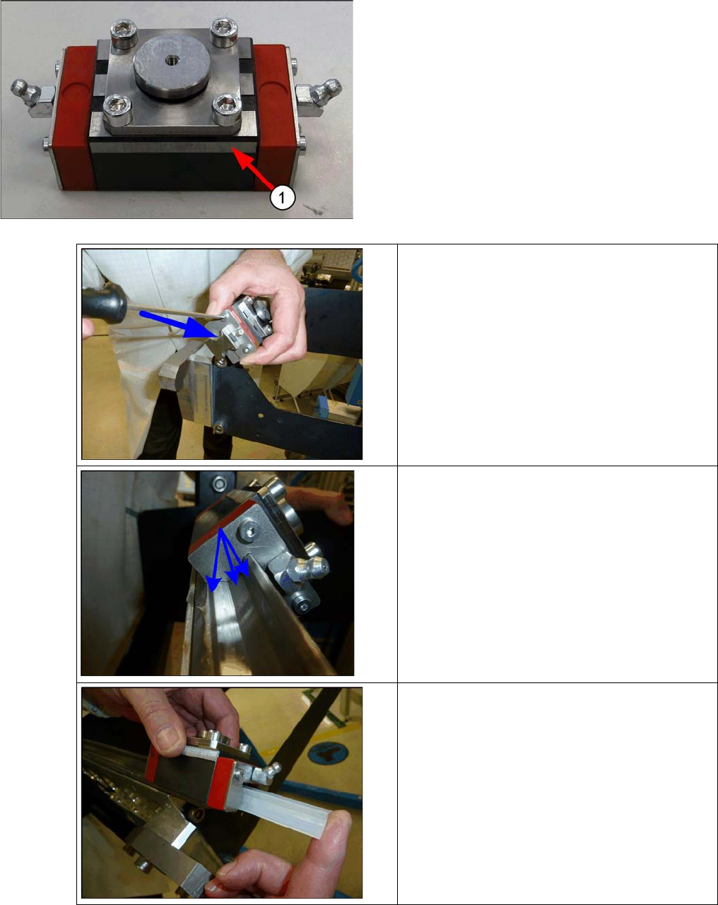
2.6.1 Prepare the guide carriage
▪ Place the "adapter with groove" 03074058-xx on the
guide carriage Y MRC 25-G2-V1 03059084-xx and fix
it with 4 DIN912-M6 x 12-8.8, verz.DSP bolts
[03046828-xx] The screws are by hand tightened.
▪ Press the adapter as shown in the image away from
the ground surface.
▪ The ground surface is later used as installation edge
at the gantry
.
▪ Tighten the screws (10Nm) and mark the position
with the "thread red lock paint" .
▪ 1. ground surface
▪ Insert the new guide carriages into the guide
rail. (for example on the gantry carrier)
▪ Ask the stripping plates so that they do not r
ub
a
gainst the guide rail. An air gap must be on
both sides between the rail and wipers .
▪
▪ Insert this again onto the plastic rail.
Service Work
Y-guide carriage / Y-loose bearing Replace Replacing the storage Cart
26 Service Manual (Internal) SIPLACE SX1/SX2/DX1/DX2
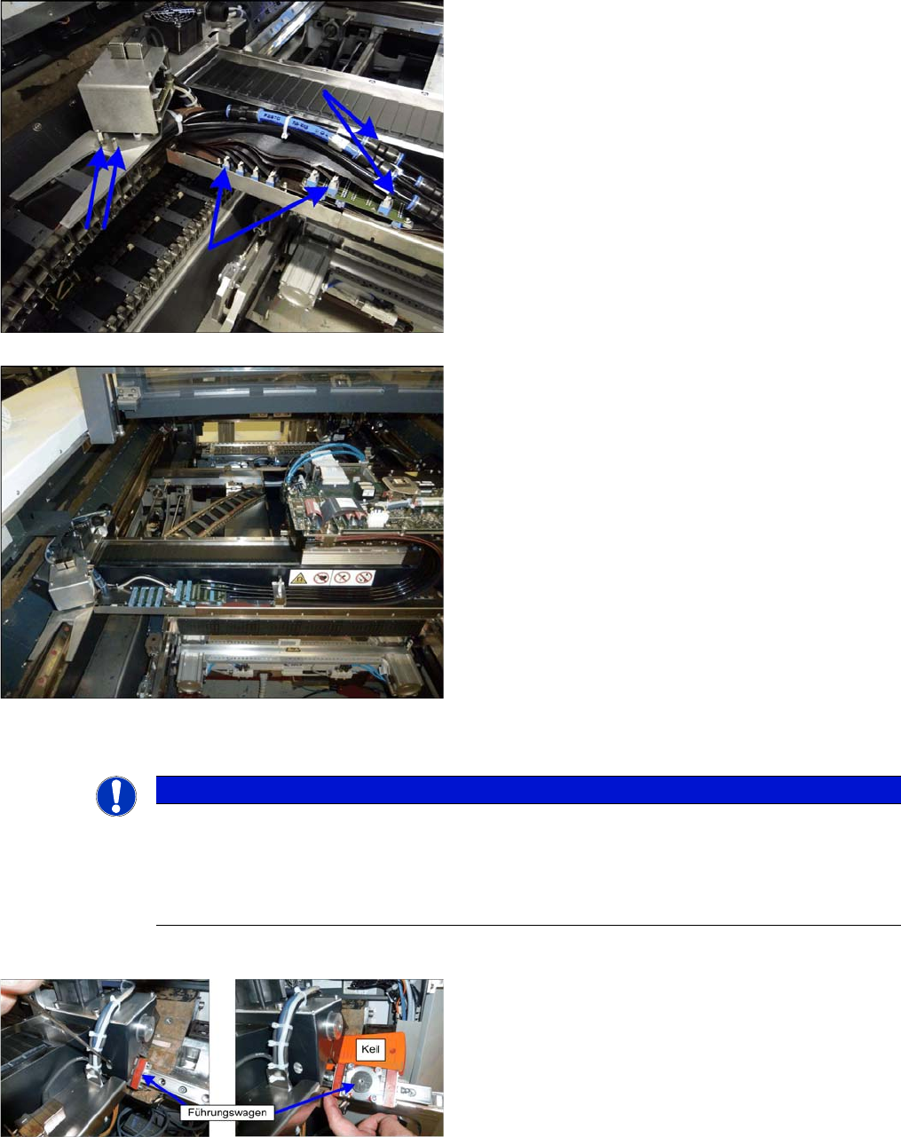
Unplug the cable trailing.
See also Chapter 3.3.12 SX1_2 Service Manual Y-trailing cable exchange [03075584-xx]
2.6.2 Replacing the storage Cart
▪ Dismantle each two magnets as described in chapter "replacement / extension of Y magnets.
▪ Unplug the ribbon cable and hose the Y-trailing cable
to the portal interface X-and Y-axis drag.
▪ Release the two hexagons spacer bolts at the Y sen-
sor module holder.
▪ Connect the trailing cable so in the machine, that it
can not be damaged, when the gantry will be moved
out of the machine.
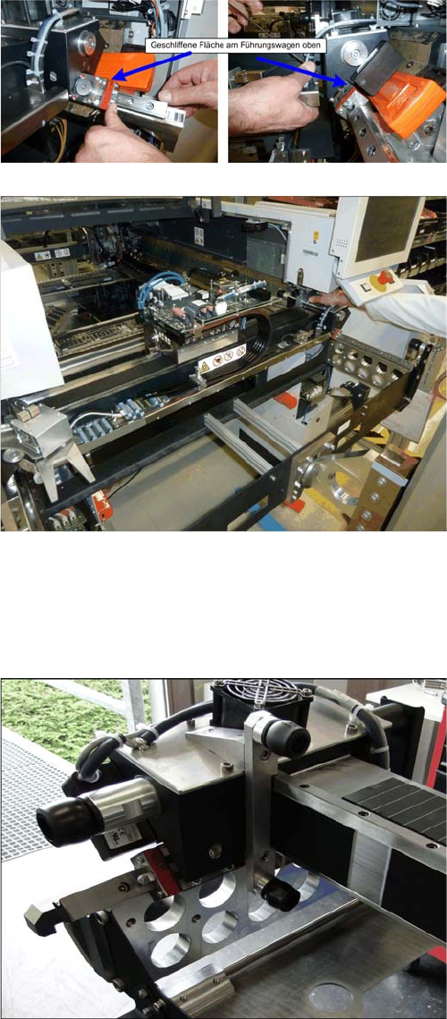
NOTICE
In certain circumstances there is a one 40μ thin slice placed underneath the adapters.These
are not part of the pact, and spare parts are placed depending gantry. If the document is placed
under the head-side or on the gantry side of the fixed bearing dependents on the hysteresis by
the gantry island fabrication. This must be used again for the new bearing. This is inserted be-
tween "adapter with groove (bearing mushroom" and gantry.
Slide the gantry to the outside, so that the magnets do not
have any effect on it anymore.
Loose the screw of the guide carriage.
Place a plastic wedge under the motor, so that you can
pull out the guide carriage. Slide the guide carriage off the
guide rail on the additional transport protection from the
spare parts kit guide carriage.
Service Work
Replacing the storage Cart Y-guide carriage / Y-loose bearing Replace
Service Manual (Internal) SIPLACE SX1/SX2/DX1/DX2 27
Slide the new guide carriages, with the cut side facing up,
onto the guide rail and the gantry.
Screw the carriage lightly. Note the truck must not be
tightened. This happens first on the gantry trough since
only there the parallels between the two carriages on the
gantry can be set.
Take the gantry as shown in the assembly instructions
gantry SIP. SX1/SX2 [00196626-xx] on the gantry carrier.
Move the placement head in the middle of the gantry.
Thereby is to ensure that the load is evenly distributed.
Fit the two transportation locks for the placement head.
The head must be in the center of the gantry.
Move the gantry lift with locked gantry carrier up to the
docking unit of the machine.
Using the docking hooks, hook the gantry carrier into the
openings of the docking unit.
Push the gantry onto the gantry carrier and make sure
that the tilt guard engages into place!
Lift the gantry lift with the gantry carrier and the gantry out
of the docking unit and move it out of the machine.
Attach the 3 transportation locks for the gantry to the gan-
try carrier! Only transport the gantry with the gantry carri-
er when all transportation locks are in place! Do not move
the gantry with the gantry carrier over long distances.
▪ Now solve the second carriage and push it back to a
free transport safety.