KE-2030使用说明书 - 第11页
1 − 2 – W indowsNT increases the operabilit y of the m achine great ly. 1.1.2 Centering sy stem Instead of using conventional mechanical cent ering system , this machine uses touchless centering system where laser align …
1 − 1
CHAPTER 1 GENERAL
1.1 Highlights and Specifications
This machine is an SMD chip shooter designed as one of the KE-2000 series products
which are successors of the KE-700 series chip placers, and features high-speed chip
placement.
A host line computer (HLC) controls a line consisting the KE-2000 series chip
placer/shooter, KE-700 series chip placer, JUKI dispenser and solder-paste printer as
well as a line consisting of KE-2000 series chip placers/shooters only. This feature
allows you to configure a line which realizes high productivity and is appropriate for
every applications.
For software, WindowsNT is adopted as the Operating System (OS) to increase the
operability of this machine.
1.1.1 Highlights
– Equipped with two sets of the newly developed laser alignment sensors (MNLA)
each of which allows four nozzles to recognize components simultaneously, and
controls the nozzles in the X direction independently. In addition, equipped with
two placement stations for transferring a board simultaneously to enable
simultaneous pick-up and placement of components by driving one of these
placement stations in the Y direction.
– Simultaneous pick-up and placement of components with two heads (total eight
nozzles) enables high-speed placement of components on the almost entire area
of a 330 mm x 250 mm board: 20,000 cph (rough estimate calculated on the
assumption that eight components are simultaneously picked up and two
components are simultaneously placed).
– An offset correction camera, a height measurement device (option), and a feeder
preparation function (option) can be installed to minimize the time required for the
machine halt for preparation, realizing high operating ratio.
– Each position offset camera attached on both of two heads uses its pattern
matching function to recognize a fiducial mark at high speed. Together with
high-speed board transfer, it provides you with an overall high-speed placement
capability.
– Pick and placement reliability is remarkably improved through chip rise detection
performed during laser/align measurement.
– The board support section (for backing up a board) is driven by a motor to prevent
any vibration from occurring when a clamped board is released, then prevent a
placed component from being shifted from the regulated position, shortening the
time required to clamp or release a board.
– Using the offset correction camera and the height measurement device,
preparation is possible without opening the cover, provided as good safety
features.
– Newly attached LED indicators (optional) (Feeder Position Indicator: FPI) on the
feeder setting section notify an operator that components run out, and generates
the warning on the number of the remaining components to increase the
operability for replacing components.
1 − 2
– WindowsNT increases the operability of the machine greatly.
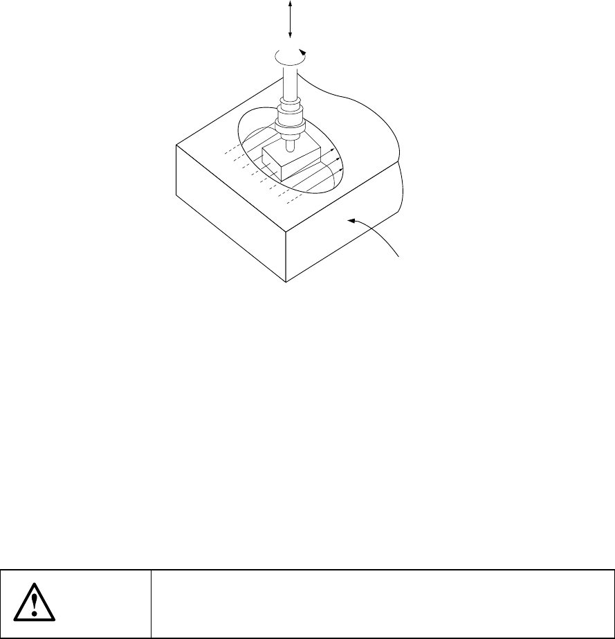
1.1.2 Centering system
Instead of using conventional mechanical centering system, this machine uses
touchless centering system where laser align sensor is used to read the position and
angle of components. This can be achieved by detecting the shade of the
components created by the laser rays applied horizontally to the components.
Z
θ
Figure 1.1.2.1
By moving Z-axis up and down, a component is picked with vacuum, and the laser is
applied to the component. A shade is made where the laser is obstructed by the
component. By turning the component along q-axis, the shade changes.
According to the change of the shade, offsets of the position and angle of the picked
component are calculated. These offsets are corrected when mounting.
The laser align sensor conforms to IEC825 Class 1 and CDRH Class 1 regulations.
The laser align sensor can be used safely as far as it is used by following the
instructions described in this manual.
CAUTION
Any operation of controls and adjustments which is not described in
this manual can cause an excessive exposure of laser lays which
may be dangerous to human bodies.
Laser align sensor
1 − 3
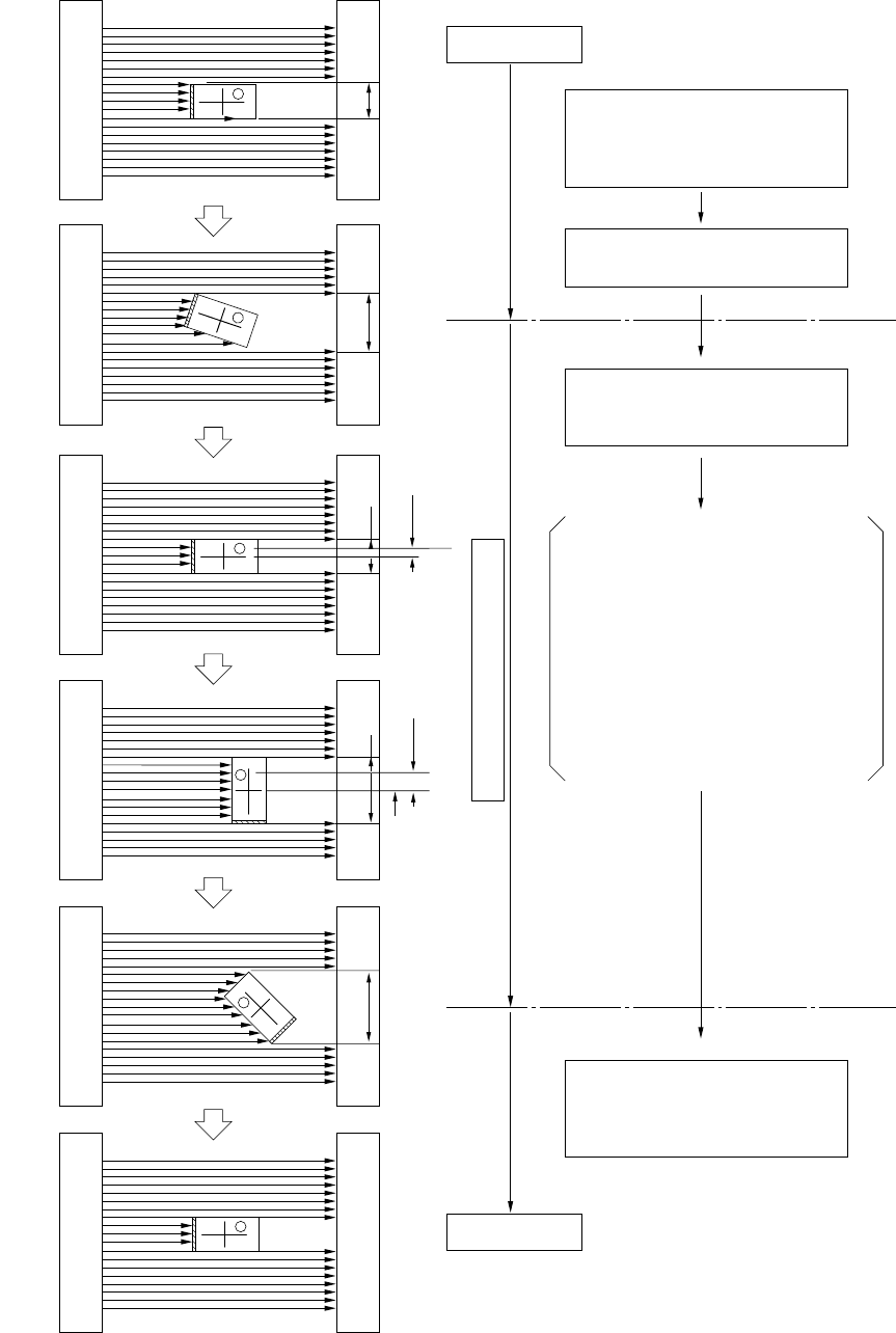
(1) Flow of laser align centering
ABCDE
(-) Rotation
(preload)
(+) Rotation
(+) Rotation
Correction
Part attracting
Placement
Correction Preload
d Yd X
Rotate in (-) direction along
θ-axis. (Preload)
Pick the component by driving
Z-axis, and adjust the
component at laser align height.
Rotate in (+) direction along
θ-axis, and start measurement
with laser align.
Placement is performed by
correcting position offset (dX,
dY) and angle offset (dθ).
While measuring the shade, find two
positions and where the shade
is minimum.
Because the nozzle center is a known
factor, according to the difference
between the nozzle center and the
component center, offset in Y direction
(dX) and that in X direction (dY) can
also be known. By referring to the
encoder output of the θ motor at or
, offset angle dθ can also be known.
(Compo-
nent
center)
(Nozzle
center)
Laser align measurement
Figure 1.1.2.2
①
②
③
④
⑤
⑥
③
④
④
③