KE-2030使用说明书 - 第184页
4 – 85 4.7.7 Tack control section (Inspection page) ① T ombstone det. Using the r adio button, select whether to use the chip r ise detecting opt ion. W hen y ou select “Y es” or “If possible”, ent er values at the item …
4 – 84
⑨ Laser algorithm
Select the algorithm for laser recognition with the combo box
Laser algorithm 0: Rotates a component from the pick-up position by the
placement angle, then places it.
(for a component which cannot be recognized with laser, but
you want to place on a board.)
Laser algorithm 1: Finds a side whose shade width is the narrowest (first
smallest shade A), then rotates a component from this side to
the + 90 degrees position. Next, detect the narrowest side
(second smallest shade B) to correct a positioning error
and/or angle error, then places the component.
(for a chip component)
Laser algorithm 2: Finds a side whose shade width is the narrowest (first
smallest shade A), then rotates a component from this side in
the positive direction while aligning it with laser. Next, detect
the narrowest side (second smallest shade B) to correct a
positioning error and/or angle error, then places the
component.
(for a component which has a lead(s) such as an SOP)
Laser algorithm 3: Detects the shade of a component which is ready for
pick-up (first smallest shade A), then rotates the component
from the detected side to the + 90 degrees position. Next,
detect the narrowest width (second smallest shade B) to
correct a positioning error, then places the component.
(for a cylindrical-shaped component)
⑩ Pre-rotate
Set how much a laser recognition component which is picked up shall be rotated
(pre-rotate angle) before it is centered. Enter the pre-rotate angle in the edit
field When you enter the dimensions for the first time, the default value is set
here. When you change them, the default value is not set.
4 – 85
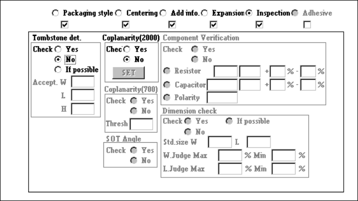
4.7.7 Tack control section (Inspection page)
① Tombstone det.
Using the radio button, select whether to use the chip rise detecting option.
When you select “Yes” or “If possible”, enter values at the items “Accept. W”, “L”
and “H” also as the reference value. If you select “If possible”, the machine
detects a chip rise error when the chip rise detecting unit is installed on the
machine.
② Coplanarity (
((
(featured in KE-2020 / 2040 only)
))
)
Specify whether to check if a lead of a component floats or not with using the
radio button.
When you check the radio button “YES”, the <Set> button is enabled.
Enter the coplanarity check data.
4 – 86
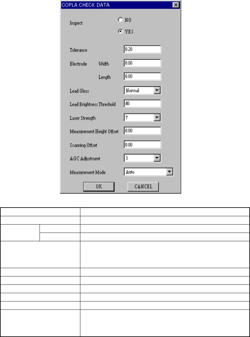
When you click the <Set> button, the following “COPLA CHECK DATA” dialog
box appears on the screen.
Inspect Select whether to perform the coplanarity check or not.
Tolerance Set the value used for judgment.
Width Set the width of the electrode.
Electrode
Length Set the length of the electrode.
Lead Gloss
Set the lead coating information.
• Normal
• Glossy
• Not glossy
Lead Brightness Threshold Set the threshold value for the brightness of a lead.
Laser Strength Set the laser strength from 0 to 7.
Measurement Height Offset Set the offset for the measured height.
Scanning Offset Set the offset for the scanned position.
AGC Adjustment Set the AGC corrected value from 0 to 5.
Measurement Mode
Set the measurement mode:
• Auto
• Normal measurement mode
• High-precision measurement mode
Click the <OK> button to validate your settings, or <CANCEL> button to cancel
your settings.