KE-2030使用说明书 - 第247页
4 – 148 4.10.2 Div ided Placement Data This command displays Placement data which is distributed to each st ation by the Optimization utilit y . Select t he menu command [ Divided Placement Data] fr om the “Optim ization…

4 – 147
− Feeder
Set the Non-stop operation of a feeder.
• No: The Optimization utility does not perform the Non-stop
operation.
• Tact priority: The Optimization utility assigns components with considering
the tact first.
• Arrange priority: The Optimization utility assigns components with considering
the feeder changeover first.
When you select “Arrange priority” with a KE-2020, an error occurs if the
system executes the line coherence check.
− Primary Secondary
Select which side to be used mainly in Non-Stop operation mode, front or rear.
• Front to Rear: The system performs PWB production with the front side mainly,
and uses the rear side when you replace components.
• Rear to Front: The system performs PWB production with the rear side mainly,
and uses the front side when you replace components.
− MTC/MTS
Select whether to allow an MTC and MTS to perform the Non-stop operation or
not.
4 – 148
4.10.2 Divided Placement Data
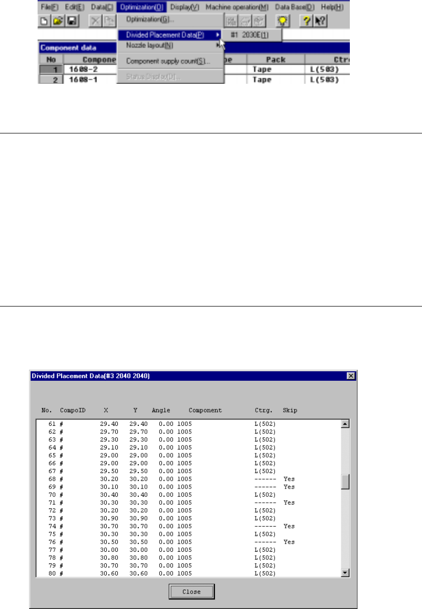
This command displays Placement data which is distributed to each station by the
Optimization utility. Select the menu command [Divided Placement Data] from the
“Optimization” menu. A submenu from which you can select stations displays. Select
a station whose data is to be displayed.
Figure 4.10.2.1 Divided Placement Data selection menu
Notes:
①
This menu cannot be selected if optimization has not been performed
(the divided files do not exist), or if the production program has been
changed after optimization.
②
The display order of divided placement data can be either in the
placement order or optimization order: the order is selected with the
[Environment Settings] command displayed on the File menu.
•
When input order is selected, all Placement data is displayed in
placement order.
•
When optimization order is selected, data on a component to be
placed only is displayed in the optimized placement order as the
result of optimization.
When you select a station on the station selection dialog box, the corresponding
window appears on the screen as shown below.
Figure 4.10.2.2 Divided Placement Data Display Example (placement Order)
4 – 149
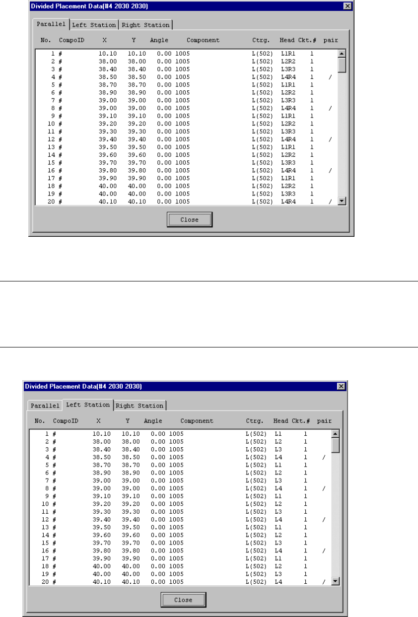
• When a KE-2030 series station is selected, three modes are displayed on the
screen: Parallel, Left Station, and Right Station.
Figure 4.10.2.3 KE-2030 Station Divided Placement Data Display Example
(When you click the “PArallel” tab)
Note:
•
When displayed in optimization order, the pair end mark “/” indicates the
separation of data paired during one pick and placement cycle of operation.
•
When you use a KE-2030, three tabs are displayed on the screen: “Both
stations” (left and right heads), “Left Station” and “Right Station”.
Figure 4.10.2.4 Divided Placement Data screen example
(KE-2030 Left station)