KE-2030使用说明书 - 第248页
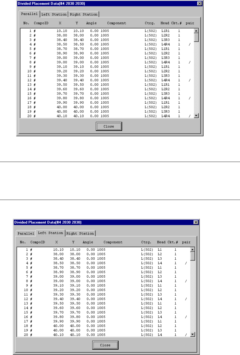
4 – 149 • W hen a KE-2030 ser ies station is selected, three modes ar e displayed on the screen: Parallel, Lef t Stat ion, and Right Station. Figure 4.10.2. 3 KE-2030 Station Divided Placement Data Di splay Exampl e (Whe…
4 – 148
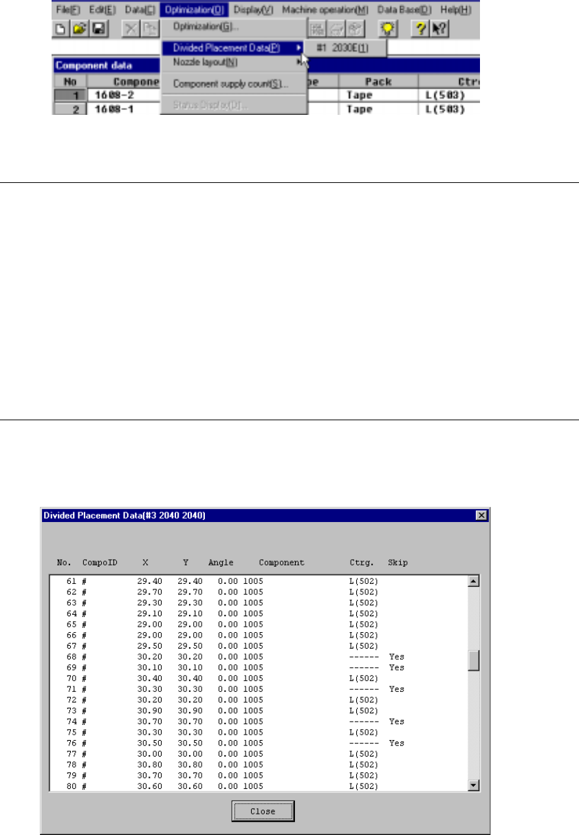
4.10.2 Divided Placement Data
This command displays Placement data which is distributed to each station by the
Optimization utility. Select the menu command [Divided Placement Data] from the
“Optimization” menu. A submenu from which you can select stations displays. Select
a station whose data is to be displayed.
Figure 4.10.2.1 Divided Placement Data selection menu
Notes:
①
This menu cannot be selected if optimization has not been performed
(the divided files do not exist), or if the production program has been
changed after optimization.
②
The display order of divided placement data can be either in the
placement order or optimization order: the order is selected with the
[Environment Settings] command displayed on the File menu.
•
When input order is selected, all Placement data is displayed in
placement order.
•
When optimization order is selected, data on a component to be
placed only is displayed in the optimized placement order as the
result of optimization.
When you select a station on the station selection dialog box, the corresponding
window appears on the screen as shown below.
Figure 4.10.2.2 Divided Placement Data Display Example (placement Order)
4 – 149
• When a KE-2030 series station is selected, three modes are displayed on the
screen: Parallel, Left Station, and Right Station.
Figure 4.10.2.3 KE-2030 Station Divided Placement Data Display Example
(When you click the “PArallel” tab)
Note:
•
When displayed in optimization order, the pair end mark “/” indicates the
separation of data paired during one pick and placement cycle of operation.
•
When you use a KE-2030, three tabs are displayed on the screen: “Both
stations” (left and right heads), “Left Station” and “Right Station”.
Figure 4.10.2.4 Divided Placement Data screen example
(KE-2030 Left station)
4 – 150
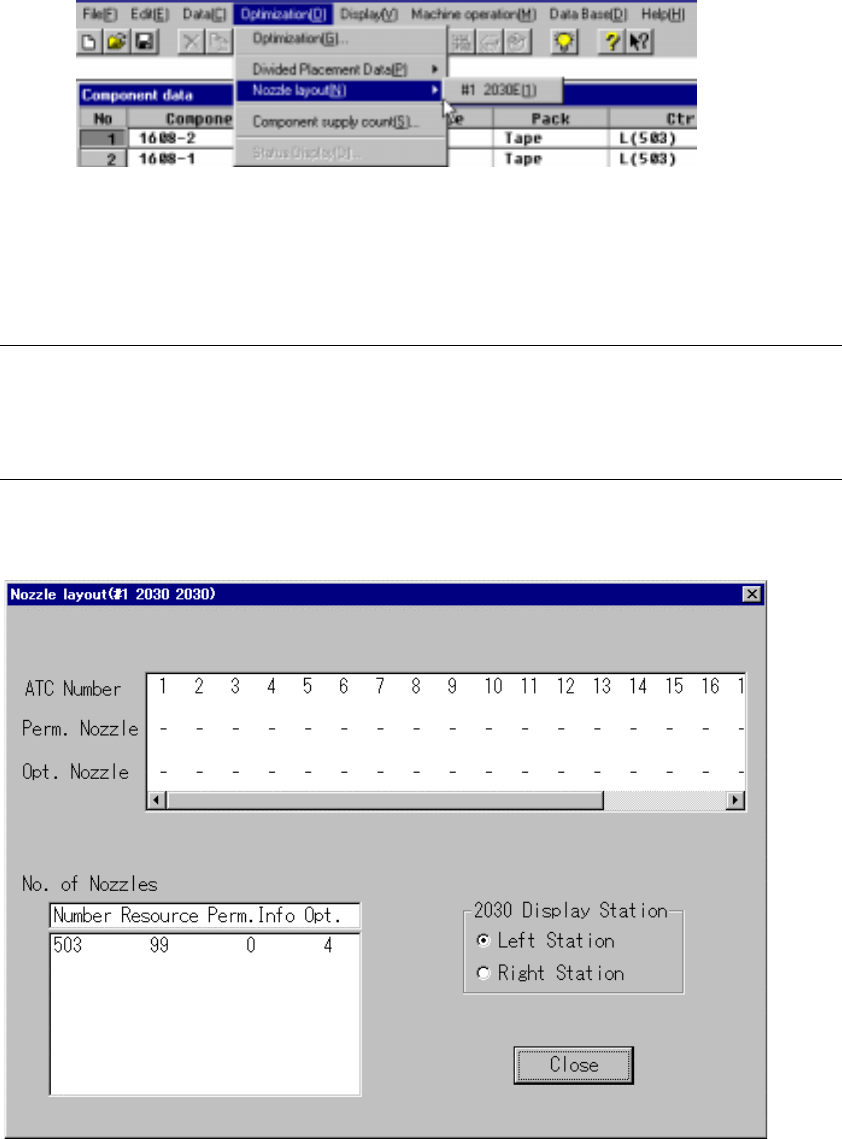
4.10.3
Nozzle layout
This command displays the nozzles assigned to each station by the Optimization
utility.
Figure 4.10.3.1 Nozzle Layout Selection
Select the “Nozzle Layout” menu command from “Optimization” menu. The sub-menu
appears which allows you to select a station. Select the desired station on this
sub-menu.
Notes:
①
This menu cannot be selected if optimization has not been preformed or
if the production program has been changed after optimization.
②
Nozzle displayed here are nozzles that are set in the Machine setup
menu and nozzle used in the program data.
The following window displays after a station is selected:
Figure 4.10.3.2 Nozzle Layout Display Example