KE-2030使用说明书 - 第27页
1 − 18 (2) Area in which backup pins cannot be proved KE-2030M 搬送レール固定側 M 基板仕様 基板搬送方向 バックアップ ピン 設置不可範囲 4mm 1 7.5mm 1 7.5mm 2 1 mm 50mm 20mm 0 ~ 90mm (可動) 22mm (搬送方向左流れ時、 20mm ) 36mm 1 05mm 0 ~ 85mm 20mm 基板裏面デッドスペース 30mm …
1 − 17
1.1.7 Printed circuit board specifications
1. Board size
Min. : X 50 mm x Y 30 mm
Note that the minimum size becomes 50 mm x 50 mm (X/Y) (optional)
when the machine is equipped with the automatic PWB width
adjustment function.
Max. : [KE-2030M] X 330 mm x Y 250 mm
[KE-2030L] X 410 mm x Y 360 mm
[KE-2030E] X 510 mm x Y 460 mm
X : Along the movement of the board
Y : From front to rear (and reversely) of the machine
2. Board thickness
Min. : 0.4 mm
Max. : 4 mm
3. Board warp limit
0.2 mm or less per 50 mm
1 mm or less both for upward and downward directions
(Conforms to JIS B 8641.)
4. Board limitations
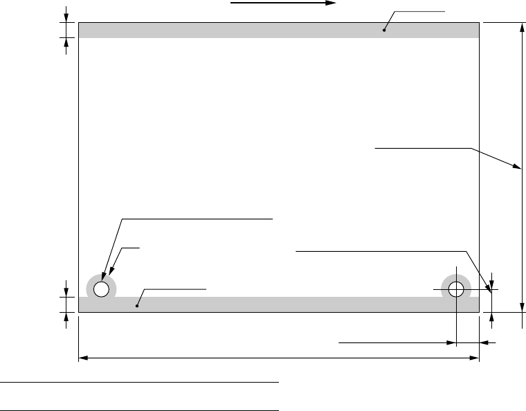
(1) Marginal area
3
3
Note: Dimension at the factory
Movement of PWB
Marginal area
Standard φ4
+0.1
mm
0
φ2.5 - φ4
+0.1
mm (Optional)
0
[KE-2030M] 30 - 250mm
[KE-2030L] 30 - 360mm
[KE-2030E] 30 - 460mm
5 ± 0.1mm
5 - 7mm for particular ordering (factory-set)
Marginal area
Conveying rail (fixed)
Standard 5 ± 0.1mm (Note)
[KE-2030M] 50 - 330mm, [KE-2030L] 50 - 410mm, [KE-2030E] 50 -510mm
1 − 18
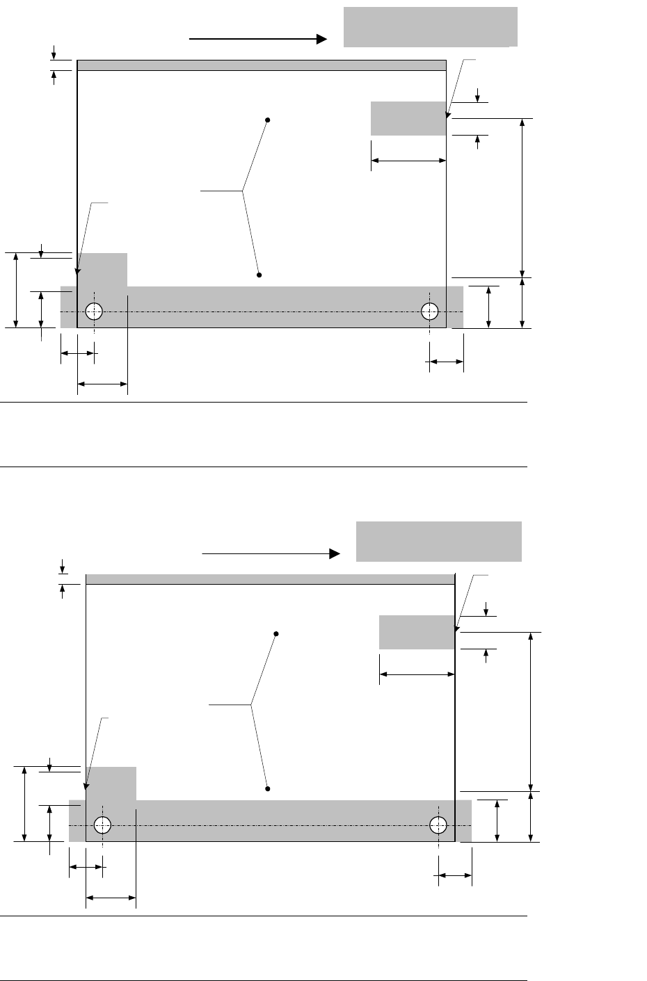
(2) Area in which backup pins cannot be proved KE-2030M
搬送レール固定側
M基板仕様
基板搬送方向
バックアップピン
設置不可範囲
4mm
17.5mm
17.5mm
21mm
50mm
20mm
0~90mm(可動)22mm
(搬送方向左流れ時、20mm)
36mm
105mm
0~85mm
20mm
基板裏面デッドスペース
30mm範囲
ストッパ設置位置
Xストッパ設置位置
Note: When the PWB is transferred from right to left, the marginal area of 50mm x
20mm is set on the left.
When the PWB is transferred from right to left, the marginal area of 36mm x
105mm is set on the right.
(3) Area in which backup pins cannot be proved KE-2030L
搬送レール固定側
L基板仕様
基板搬送方向
バックアップピン
設置不可範囲
4mm
17.5mm
17.5mm
21mm
50mm
20mm
0~178mm(可動)37mm
(搬送方向左流れ時、35mm)
36mm
105mm
0~85mm
20mm
基板裏面デッドスペース
30mm範囲
ストッパ設置位置
Xストッパ設置位置
Note: When the PWB is transferred from right to left, the marginal area of 50mm x
20mm is set on the left.
When the PWB is transferred from right to left, the marginal area of 36mm x
105mm is set on the right.105mm is set on the right.
Movement of PWB
X stopper position
Stopper position
Dead zone of the rear of a PWB:
within the 30 mm-area
Conveying rail (fixed)
Area in which backup
pins cannot be provided
(Variable)
(20 mm when the
PWB is
transferred from
Movement of PWB
Stopper position
Area in which backup
pins cannot be provided
Movement of PWB
Stopper position
Area in which backup
pins cannot be provided
X stopper position
Conveying rail (fixed)
(Variable)
Dead zone of the rear of a PWB:
within the 30 mm-area
(35 mm when the
PWB is
transferred from
1 − 19
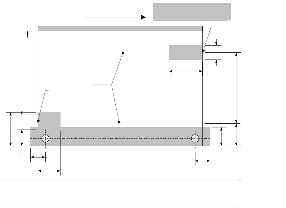
(4) Area in which backup pins cannot be proved KE-2030E
搬送レール固定側
E基板仕様
基板搬送方向
バックアップピン
設置不可範囲
4mm
17.5mm
17.5mm
21mm
50mm
20mm
0~220mm(可動)37mm
(搬送方向左流れ時、35mm)
36mm
105mm
0~85mm
20mm
基板裏面デッドスペース
30mm範囲
ストッパ設置位置
Xストッパ設置位置
Note: When the PWB is transferred from right to left, the marginal area of 50mm x
20mm is set on the left.
When the PWB is transferred from right to left, the marginal area of 36mm x
105mm is set on the right.
Movement of PWB
X stopper position
Stopper position
Dead zone of the rear of a PWB:
within the 30 mm-area
Conveying rail (fixed)
Area in which backup
pins cannot be provided
(Variable)
(35 mm when the
PWB is
transferred from
Movement of PWB
Stopper position
Area in which backup
pins cannot be provided