KE-2030使用说明书 - 第32页
1 − 23 3 1 5 4 1 2 5 Figure 1.2.1. 3 ① ATC unit ④ PW B transfer unit ② Head unit ⑤ Feeder bank unit ③ X-Y unit
1 − 22
1.2 Basic Configuration and Parts Identification
1.2.1 Entire system views
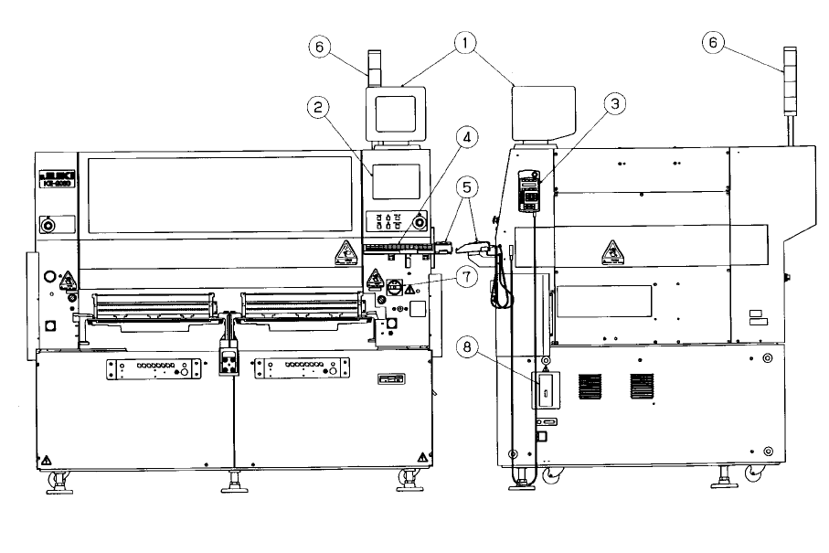
Figure 1.2.1.1 Front View Figure 1.2.1.2 Right Side View
① Vision monitor ⑤ Track ball
② LCD display ⑥ Signal tower
③ HOD unit ⑦ Main switch
④ Keyboard ⑧ No-fuse breaker
1 − 23
3
1
5
4
1
2
5
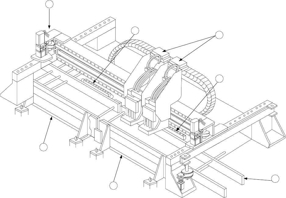
Figure 1.2.1.3
①
ATC unit
④
PWB transfer unit
②
Head unit
⑤
Feeder bank unit
③
X-Y unit
1 − 24
1.2.2 PWB transfer unit: mechanism and parts identification
1. Pin reference
1) When the first board is carried in, the IN sensor ① detects the board.
2) The IN motor ④ is driven to start feeding the board.
3) When the Wait sensor detects the board, the stopper at the exit
24
turns on,
the C.board chuck cylinder
32
and S board chuck cylinder
33
turn off in this
order.
4) When the stop sensor at the exit ⑲ detects the board, the machine stops
feeding it, then moves up the BU table at the exit
28
to position and fix the
board with this table and the centering pin at the exit
27
.
5) The second board waits at the Wait sensor ③.
6) When the C.OUT sensor at the entrance ⑦ detects the first board, the
stopper at the entrance ⑪ turns on.
7) The center motor at the entrance ⑧ is driven to start feeding the second
board.
8) When the stopper sensor at the entrance ⑥ detects the second board, the
machine stops feeding it, then moves up the BU table at the entrance ⑮ to
position and fix the board with this table and the centering pin at the entrance
⑭.
9) The third board waits at the Wait sensor ③.
2. Edge reference
The board transfer mechanism is the same as that of the pin reference above.
When the board is fixed, edges of the boards are held by the X pusher at the
entrance ⑫, Y pusher at the entrance ⑬, X pusher at the exit
25
and Y pusher
at the exit
26
. The transfer operation that follows is also the same as that of the
pin reference above.