KE-2030使用说明书 - 第45页
1 − 36 (3) Minimum component width (D) of each com ponent. !1 A D A D W D A D = A A D A D A D A D D A D = A A A A D = A A A D = A A D A D A D ① Square chip ② MEL F ③ Aluminum electrolytic capacitor D = A + 0.5mm ④ SOT ⑤ …

1 − 35
(2) Nozzle selection
The nozzle can be automatically recognized if you follow the explanation of "3.4.1
ATC Nozzle Selection". If you manually select the nozzle, select the nozzle with
extreme care to prevent poor pickup and placement of a compornent.
The nozzle numbers for major types of components to placed be are shown in
Table 1.2.6.2. However, to keep accuracy of pickup and placement, select the
appropriate nozzle No. by referring to the minimum size of the suction area of
each component.
See the item (3) for the minimum width (D) of the sucked area of each
component.
Table 1.2.6.2 Nozzles and their pickable minimum component width
Nozzle
No.
Minimum
component
width (D)
Major types of components Applicable
components to
be placed
500
501
502
503
504
505
506
507
508
0.45 to 1.45
to 0.45
0.45 to 0.75
0.75 to 1.45
1.1 to 2.5
2.5 to 4
4 to 7
7 to 10
10 or more
1005, 1608, SOT(Molded part: 1.6 x 0.8),
SOT(Molded part: 2.0 x 1.25)
0603
1005
1608、SOT(Molded part: 1.6 x 0.8), 2012,
SOT(Molded part: 2.0 x 1.25)
2012, 3216, SOT(Molded part: 2.0 x 1.25), SOT23,
Aluminum electrolytic capacitor
(small), tantalum capacitor, trimmer
Aluminum electrolytic capacitor
(medium), SOP (narrow type), SOJ, connector
Aluminum electrolytic capacitor
(large), SOP (wide type), TSOP, QFP, PLCC, SOJ,
connector
QFP, PLCC
3225, tantalum
capacitor
1 − 36
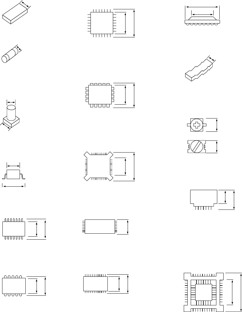
(3) Minimum component width (D) of each component.
!1
A
D
A
D
W
D
A
D = A
A
D
A
D
A
D
A
D
D
A
D = A
A
A
A
D = A
AA
D = A
A
D
A
D
A
D
① Square chip
② MELF
③ Aluminum
electrolytic capacitor
D = A + 0.5mm
④ SOT
⑤ SOP
⑥ SOJ
⑦ QFP ⑫ BGA
⑧ PLCC
⑨ BQFP
⑩ TSOP
⑪ TSOP2
⑬ Network resistor
⑭ Trimmer
⑮ One-way lead connector
⑯ Gull wing socket
J lead socket
Socket with bumper
1 − 37
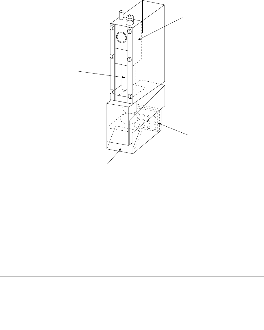
1.2.7 OCC parts identification
(1) Offset correction camera
The machine is equipped with a coaxial light and polarizing filter as the standard
devices. The camera detects a BOC mark and corrects the detected mark
automatically.
① OCC camera
② OCC lens
③ Illumination LED board
④ Mirror box
Figure 1.2.7.1
Adjusting the polarizing filter
1) Place a white ceramic board on the calibration block, then move the camera over
this board.
2) Loosen the screw to turn the filter holder to the right and left. When the screen
becomes brightest, fix the screw.
②
①
④
③