KE-2030使用说明书 - 第47页
1 − 38 1.3 X, Y, and Z A xes Descriptions The f ollowing four axes (X, Y, Z, and θ ) are num erically controlled in t his machine. (1) X- and Y-axis The X-axis and Y-axis represent the position of the head, OCC, HMS (Hei…
1 − 37
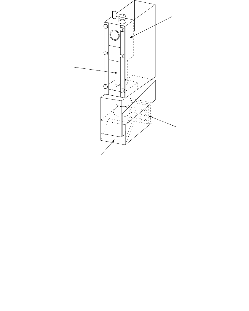
1.2.7 OCC parts identification
(1) Offset correction camera
The machine is equipped with a coaxial light and polarizing filter as the standard
devices. The camera detects a BOC mark and corrects the detected mark
automatically.
① OCC camera
② OCC lens
③ Illumination LED board
④ Mirror box
Figure 1.2.7.1
Adjusting the polarizing filter
1) Place a white ceramic board on the calibration block, then move the camera over
this board.
2) Loosen the screw to turn the filter holder to the right and left. When the screen
becomes brightest, fix the screw.
②
①
④
③
1 − 38
1.3 X, Y, and Z Axes Descriptions
The following four axes (X, Y, Z, and θ) are numerically controlled in this machine.
(1) X- and Y-axis
The X-axis and Y-axis represent the position of the head, OCC, HMS (Height
measurement system), and bad mark sensor. The coordinates of a position are
given as X = ○○○. ○○ mm and Y = ○○○. ○○ mm, in 0.01-mm
increments.
Two coordinate systems are available: software coordinates and tooling-pin (hole
reference) coordinates. Software coordinates mainly show the pickup position
taught in the teach mode, while tooling-pin coordinates represent the placement
position.
(2) Z-axis
The Z-axis represents the position of the nozzle in the head, given as Z =
○○.○○ mm, in 0.01-mm increments. The upward direction is positive (+),
with the position of the nozzle tip on the board being 0.
(3) θ-axis
The q-axis represents the angle for centering of the head "A = ○○.○○
degrees" (in 0.05 increments.) The value is positive for counterclockwise
rotation and negative for clockwise rotation.
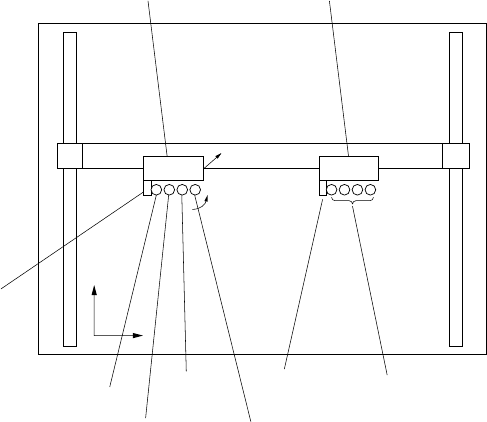
Figure 1.3.1
L head unit R head unit
X axis
Y axis
Z+
Y+
X+
OCC-L
L1 nozzle axis
L2 nozzle axis
OCC-R
L3 nozzle
axis
L4 nozzle axis
From the left,
R1 nozzle axis,
R2 nozzle axis,
R3 nozzle axis,
R4 nozzle axis
1 − 39
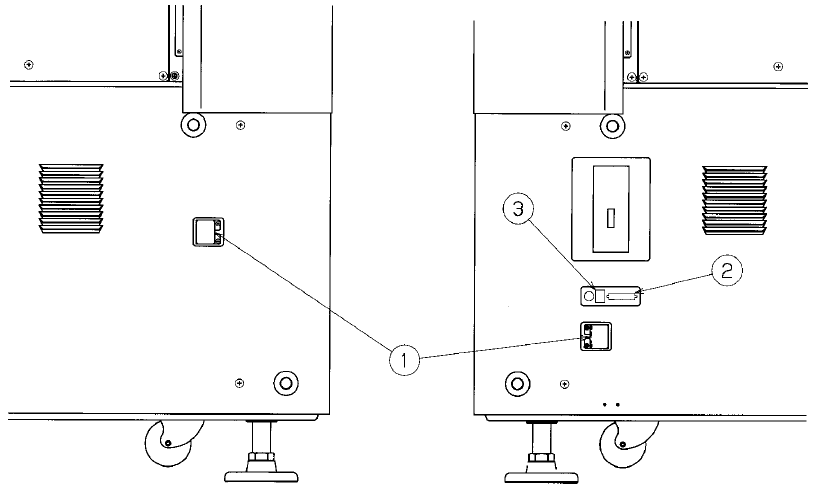
1.4 Interface With Extenal Devices
① is the 14-Pin READY OUT (IN) connector for use when the machine is configured
with other equipment in an on-line environment.
The pin layout (assignment) of the connector for a Ready OUT (IN) signal differs as
shown in Tables 1.4.1 and 1.4.2 depending on the board transfer direction (from left
to right, and from right to left, respectively).
See Table 1.4.3 for the pin assignment of this printer connector.
② is a DSub 25-Pin connector for the printer (conforming to the Centronics Interface
standards).
③ is an Ethernet connector (8-pin modular type connector).
See Table 1.4.6 for the pin assignment of this Ethernet connector.
Figure 1.4.1 Left side panel of the main unit Figure 1.4.2 Right side panel of the main
unit