KE-2030使用说明书 - 第527页
7 − 33 7.2.2.10 Vacuum table W hen y ou select [V acuum table] f rom the [Sett ing Gr oup] menu, t he “V acuum t able” dialog box appears as shown in Figure 7.2. 2.10.1. Figure 7.2.2. 10.1 “V acuum table” dialog box (1) …

7 − 32
② Units of delay
− With using the radio button, select the unit for delay.
− When you select “time”, the value you selected with the item “Delay for
conveyor sensor” is handled as the “delay time” in the unit of ms.
− When you select “length”, the value you selected with the item “Delay
for conveyor sensor” is handled as the “delay distance” in the unit of
mm.
Note: When you change the setting of this "Units of delay", the setting of the item 1
"Delay for conveyor sensor" is cleared.
③ AWC
− This item can be set in the range from - 5.00 to 5.00.
④ PWB wait time (Initial value)
− This can be set in the range from 1 to 600 (default: 60).
⑤ PWB place rate
− Set a value from 0 to 100 (default: 50). (For a KE-2030 only)
− Unit is fixed to %.
⑥ Setting head
− With using the radio button, specify the left station or right station (only
for the KE-2030).
⑦ Under Limit for conveyor
− Specify the value in the range from 5 to 30 (for the KE-2030 only).
− The unit is fixed to “mm”.
⑧ Down Acceleration
− With using the radio button, set one of three steps: Low, Medium, and
High (default setting: High).
⑨ Press In
− Specify the value in the range from 0.00 to 5.00.
7 − 33
7.2.2.10 Vacuum table
When you select [Vacuum table] from the [Setting Group] menu, the “Vacuum table”
dialog box appears as shown in Figure 7.2.2.10.1.
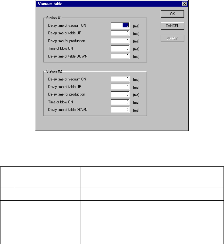
Figure 7.2.2.10.1 “Vacuum table” dialog box
(1) Setting items
No. Item Description
1 Delay time of vacuum ON Sets the time of period since the STOP sensor is activated until
vacuum is turned on when a board is clamped.
2 Delay time of table UP Sets the time of period since vacuum is turned on until the support
plate starts moving up when a board is clamped.
3 Delay time for production Sets the time of period required to detect the ON status of the vacuum
sensor when a board is clamped.
4 Time of blow ON Sets the time of period while the blow function is set to ON when the
clamped board is released.
5 Delay time of table DOWN Sets the time of period since the system detects the vacuum sensor
OFF status until the support plate starts moving down when the
clamped board is released.
(2) How to set
− Enter a value directly form a keyboard.
− The input range is from 0 to 1000.
− The unit is fixed to “ms”.
− The defaults of all the items are “0 ms”.
− When the “Vacuum table” is set to “disable” on the “Option Device enable”
tab, these menu items are dimmed.
7 − 34
7.2.2.11 Signal light
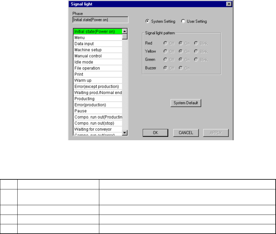
A screen as shown in Figure 7.2.2.11.1 “Signal light setting dialog box” appears
when [Signal light] is selected on the [Setting Group] menu.
Figure 7.2.2.11.1 Signal light setting dialog box
(1) Setting items
No. Item Description
1 Signal light pattern
(Red, Yellow, Green)
Sets the light pattern of the signal light in each operation phase.
2 Signal light pattern (Buzzer) Sets ON/OFF of the buzzer in each operation phase.
3 System setting/User setting Sets the data used for a user signal pattern.
4 System Default Copies the system setting data to the user setting data.
(2) How to set
① Signal light (Red, Yellow, Green)
− Using the radio button, set on, off, or blink.
② Buzzer
− Using the radio button, set off or on.
③ System Setting/User Setting
− Select the data to be used with either of these radio buttons.
− Selection of the “System Setting” radio button allows you to see the
settings of the system initial values only. You cannot change them.