KE-2030使用说明书 - 第53页
1 − 44 Table 1.4.5 The t rackball connector pin assi gnments Signal name Connector us ed 1 DATA 2 N.C. 3 GND 4 + 5V 5 CLOCK 6 N.C. Japan crimping terminal MD-S6000-13 Table 1.4.6 Ethernet connector pin assi gnments Signa…
1 − 43
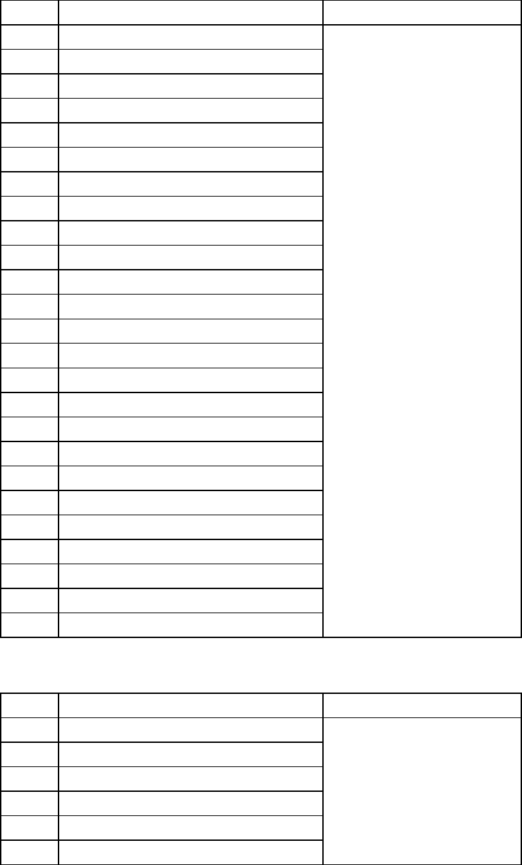
Table 1.4.3 The printer connector pin assignments
Signal name Connector used
1 STROBE
2 D0
3 D1
4 D2 D-SUB
5 D3 25-Pin FEMALE
6 D4
7 D5
8 D6
9 D7
10 ACK
11 BUSY
12 PE
13 SLCT
14 AUTFD
15 ERROR
16 INIT
17 SLCT IN
18 GND
19 GND
20 GND
21 GND
22 GND
23 GND
24 GND
25 GND
Table 1.4.4 The keyboard connector pin assignments
Signal name Connector used
1 DATA
2 N.C.
3 GND
4 + 5V
5 CLOCK
6 N.C.
Japan crimping terminal
MD-S6000-13
1 − 44
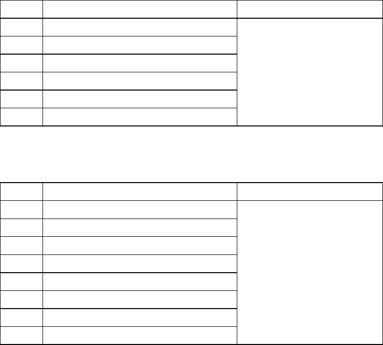
Table 1.4.5 The trackball connector pin assignments
Signal name Connector used
1 DATA
2 N.C.
3 GND
4 + 5V
5 CLOCK
6 N.C.
Japan crimping terminal
MD-S6000-13
Table 1.4.6 Ethernet connector pin assignments
Signal name Connector used
1
TD+
2
TD-
3
RD+
4
N.C.
5
N.C.
6
RD-
7
N.C.
8
N.C.
Connector used
Modular connector 8-pin
1 − 45
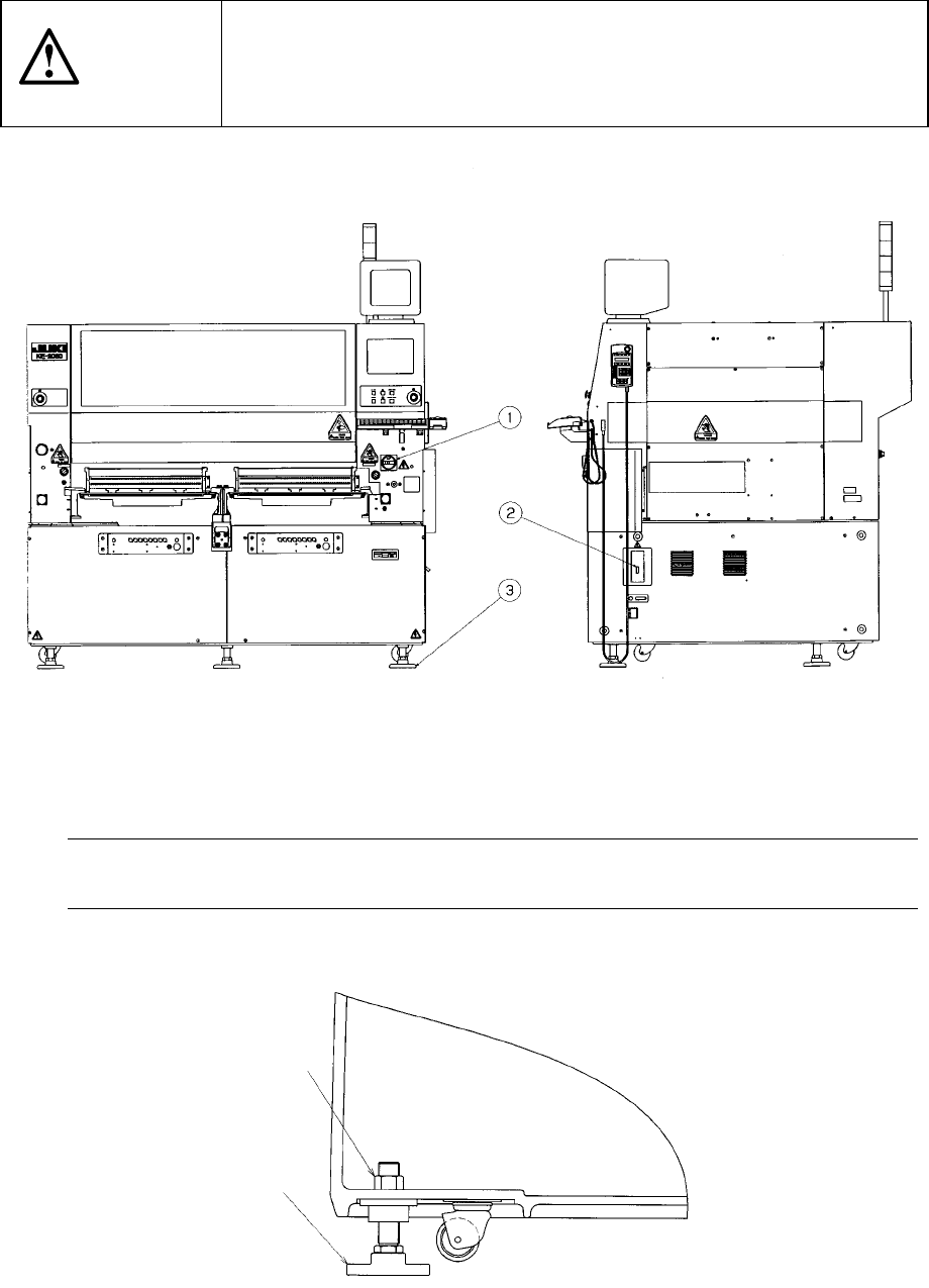
1.5 Installation Check
CAUTION
Check that the machine is level lying completely flat on the floor.
Check that the lock nuts are tightened securely on the four feet of the
machine.
Check that correct electrical power and air are supplied to the machine.
① Main switch ② Breaker ③ Adjuster ④ Pressure gauge
The pressure gauge ④ indicates the pressure of air supplied inside the main unit.
Note: To avoid the laser sensor detection error, install the machine where not subject
to direct sunlight.
Figure 1.5.1
Figure 1.5.2
Lock nut
(Six)
③