KE-2030使用说明书 - 第533页
7 − 39 ◇ ◇ ◇ ◇ Support plate The same extended menu appear s on the screen when you select either of the menu it ems "Support plate 1" and "Support plat e 2". ◇ ◇ ◇ ◇ Shape cl amp The same extended me…
7 − 38
7.3 Mechanical Setup
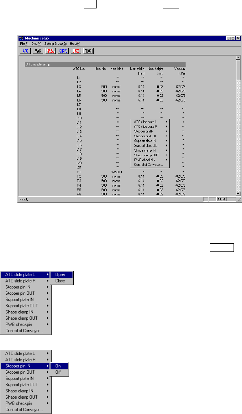
If you have to drive a mechanical device while setting the menu items on the Machine
Setup menu, display the pop-up menu for mechanical devices. Press the right button
of the trackball, or press the F10 key while holding the Shift key. A pop-up menu
shown in Figure 7.3.1 starts up.
Figure 7.3.1 Machine setup pop-up menu
When you select each menu item on the pop-up menu above, the corresponding
extended menu appears as shown below. Select a desired item on this extended
menu with a trackball, or select it with the cursor keys, then press the ENTER key to
drive the corresponding mechanical device.
◇
◇◇
◇ATC slide plate
The same extended menu appears on the screen when
you select either of the menu items: "ATC slide plate 1"
and "ATC slide plate 2".
◇
◇◇
◇Stopper pin
The same extended menu appears on the screen when
you select either of the menu items: " 1" and "Stopper
pin 2".
7 − 39
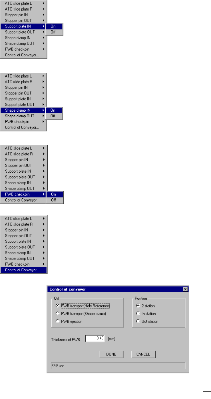
◇
◇◇
◇Support plate
The same extended menu appears on the screen when
you select either of the menu items "Support plate 1" and
"Support plate 2".
◇
◇◇
◇Shape clamp
The same extended menu appears on the screen when
you select either of the menu items "Shape clamp 1" and
"Shape clamp 2".
◇
◇◇
◇PWB check pin
◇
◇◇
◇Control of Conveyor
When you select the menu item "Control of Conveyor", no
extended menu appears on the screen and the dialog box
appears instead as shown in the figure below.
● If you select the menu item [Control of Conveyor], specify the desired control item with
the corresponding radio button, then click the <Done> button or press the F3 key.
8 − 1
CHAPTER 8 MANUAL CONTROL
8.1 Overview
The following table shows the manual control items.
Table 8.1.1 Manual control items
Main menu Sub menu Description
1 Head control XY axes movement control and display in X and Y
coordinates relative to each head.
Z and θ axes movement control and coordinate display of
each head Vacuum control, blow control, and pressure
value display of each head.
2 Head device
control
XY axes movement control and display in X and Y
coordinates of each head device (OCC, bad mark sensor,
HMS).
Control of each head device and display of sensor status
1 Head
3 Laser control Vacuum control of each head, and vacuum ON/OFF display
Z axis movement control and coordinate display of each
head algorithm change
Measurement and result display
Image display
Edge check and Edge check display
1 Independent
control of
conveyor
Stopper control, edge reference cylinder control, support
table control, ready out control, board available out control,
transport motor control, each sensor of transport system,
signal status display, support table stopper sensor control,
and Entrance (IN)/Exit (OUT) shutter control
2 Automatic control
of conveyor
Automatic transport control, each sensor of transport
system, signal status display, and movement control
between the PWB stations
3 Auto width
conveyor control
Automatic PWB width alignment operation control, display
of the PWB transport width
Status display of each conveyor sensor
4 Movable station
control
Control of the cylinder which checks if there is a PWB,
display of the cylinder and sensor status, control of the Y
axis movable station and display of coordinates
2 Conveyor
5 Vacuum Table Control of vacuum of the vacuum table, control of the blow
function, and control of the support table.
3 Vision 1 VCS control Control of the light and state display
Control of the side light board up/down cylinder and state
display
1 MTC control Shuttle control, tray control, pick control, and status display
Control of the PWB transport width adjustment operation
and display of the PWB transport width
2 MTS control Tray control and status display
4 Feeder
3 Knock pin control Control of the feeder knock pin and control of the feeder
position indicator
1 ATC control ATC slide plate control, sensor status display, and nozzle
suction control
2 Signal light control Signal light control, buzzer control, and status display
3 Component
verification
Probe control, component measurement, and status display
4 SOT inspect unit Vacuum control and state display
5 Calibration block
control
LED control, vacuum control and state display
6 Other sensors Status display of IC component discarding conveyor stop
sensor, etc.
5 Others
7 Driver state Status display of the X, Y, Z, and theta axes drivers