KE-2030使用说明书 - 第54页
1 − 45 1.5 Installation Check CA UTION Check that the machine is level ly ing completely flat on the floor. Check that the lock nuts are tightened securely on t he four feet of the machine. Check that correct electrical …
1 − 44
Table 1.4.5 The trackball connector pin assignments
Signal name Connector used
1 DATA
2 N.C.
3 GND
4 + 5V
5 CLOCK
6 N.C.
Japan crimping terminal
MD-S6000-13
Table 1.4.6 Ethernet connector pin assignments
Signal name Connector used
1
TD+
2
TD-
3
RD+
4
N.C.
5
N.C.
6
RD-
7
N.C.
8
N.C.
Connector used
Modular connector 8-pin
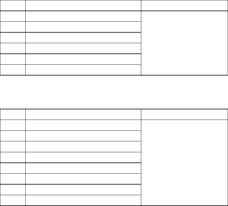
1 − 45
1.5 Installation Check
CAUTION
Check that the machine is level lying completely flat on the floor.
Check that the lock nuts are tightened securely on the four feet of the
machine.
Check that correct electrical power and air are supplied to the machine.
① Main switch ② Breaker ③ Adjuster ④ Pressure gauge
The pressure gauge ④ indicates the pressure of air supplied inside the main unit.
Note: To avoid the laser sensor detection error, install the machine where not subject
to direct sunlight.
Figure 1.5.1
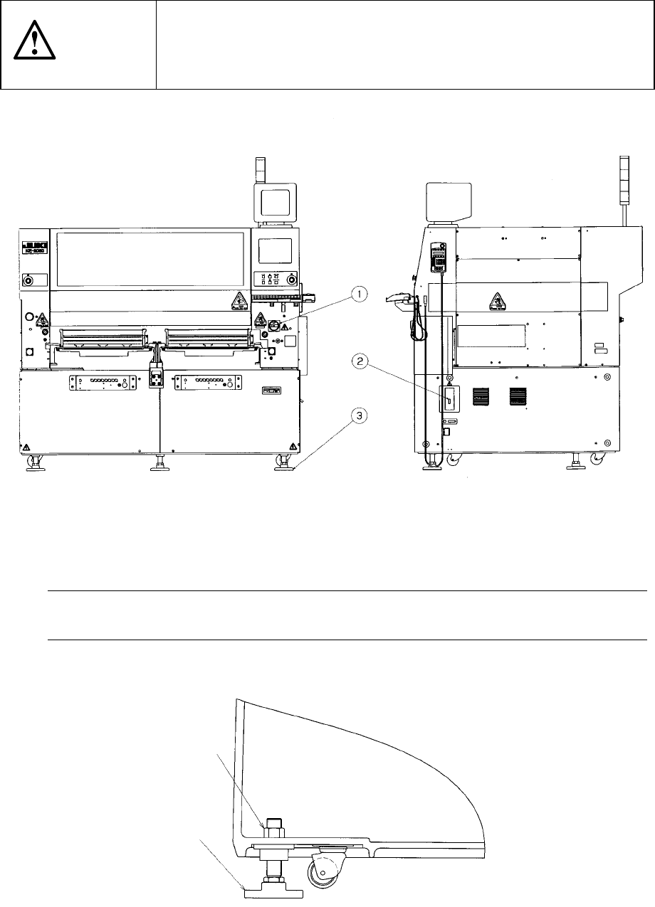
Figure 1.5.2
Lock nut
(Six)
③
1 − 46
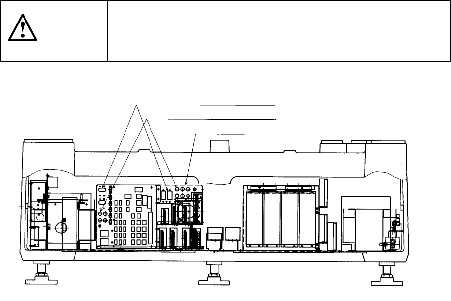
1.6 Checking circuit protector
If the machine does not operate properly after it has been turned ON, check the
condition of the circuit protector in the power unit found on the back side of the
machine. If push-button type the circuit protector front face protrudes to show the
red mark, push the face back in. When the lever of the lever-type circuit protector is
lowered, raise it.
CAUTION
To avoid risk of serious injury or death caused by electric shock hazard,
turn off the main power switch of the house current which is installed in
the building where the machine is used.
Note that it is not the main power switch of the machine.
Figure 1.6.1
Lever-type circuit protectors
Push-button type circuit protectors
Power unit