KE-2030使用说明书 - 第680页
12 − 9 Mounting 1) I nstall each f eeder in the f eeder bank ② . 2) Check that t he selector ⑥ is set to OFF, and the bank lift er u is set below the bank stopper ⑧ . 3) I nsert t he overall feeder exchang e trolley ① in…
12 − 8
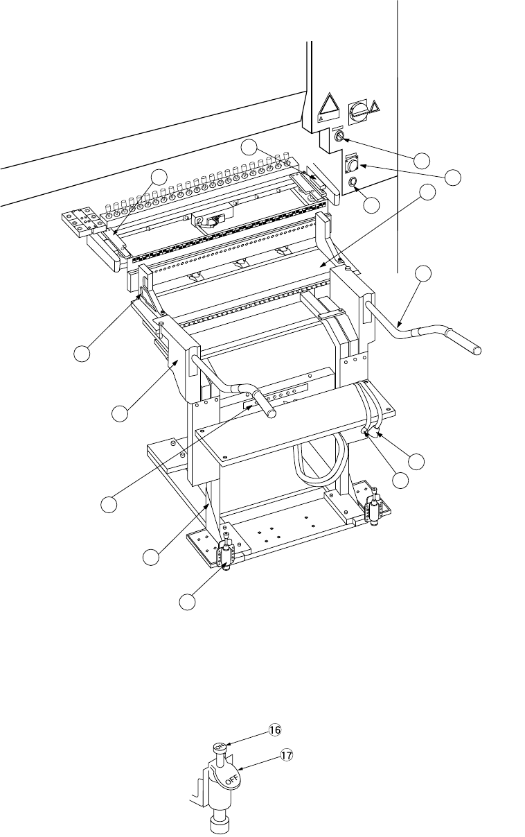
12.7 Replacing Overall feeder exchange trolley
3
9
11
1
5
4
8
7
6
13
15
2
14
12
Figure 12.7.1 Overall feeder exchange trolley
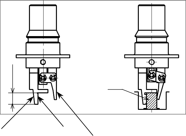
Figure 12.7.2 Trolley stopper t
⑯ Lock pedal
⑰ Lock release pedal
12 − 9
Mounting
1) Install each feeder in the feeder bank ②.
2) Check that the selector ⑥ is set to OFF, and the bank lifter u is set below the
bank stopper ⑧.
3) Insert the overall feeder exchange trolley ① into the chip shooter main unit until
the trolley stopper plate ⑪ touches the bank stopper ⑧.
4) Lock the trolley stoppers ⑤ at the left and right.
5) Set the selector ⑥ to ON. The feeder bank ② goes up and is installed in the
chip shooter main unit.
CAUTION
To avoid any accident caused by sudden activation of the machine,
turn off the power, close the air cock, and release the remaining air
before starting installation.
6) Insert the feeder connector ⑫ into the power supply ⑬ of the cover of the chip
shooter main unit. Then, insert the air coupler ⑭ into the female union ⑮ of
the cover of the chip shooter main unit.
Note: If you operate the machine even though one of the front, rear, left and
right stations of the overall feeder exchange trolley descends, the X and
Y axes move at the lower speed as if the cover is open.
Dismounting
1) Detach the air coupler and the feeder connector from the chip shooter main unit.
2) Set the selector to OFF.
The feeder bank goes down, and it comes off from the chip shooter main unit.
CAUTION
To prevent your body from injury and to avoid damage to the machine,
install the overall feeder exchange trolley only after the machine is
stopped completely.
Do not place your hand in the machine, nor move your face or head
close to the machine when operating the selector.
When operating the selector, be sure to check the selector so that you
cannot operate other switches, especially main power switch by
mistake.
3) Release the lock of the trolley stoppers at the left and right.
Note: If you use the overall feeder exchange trolley to attach the feeder bank
on the main unit of the machine, do not touch the grip
④
of the overall
feeder exchange trolley or do not impose any load on it while the
system is teaching the component pick-up position on each feeder or
while it is producing a PWB.
12 − 10
12.8 Handling a Gripper Nozzle
This nozzle is designed exclusively for the KE-2000 series of products to pick up
and/or place on a board a component whose top has no picked-up area, and it is
available to laser and vision recognition.
1. Features
The gripper nozzle uses its “fixed arm” and “swing arm” together exclusively to
pick up and/or place a component whose topside has no picked-up area. Its grip
strength is appropriate enough to pick up/place a component stably.
① Fixed arm
② Swing arm
Figure 12.8.1 Name of each part of a nozzle
①
①①
①
②
②②
②
Com
p
onent
Position against a
component is pushed
Length of a lug