KE-2030使用说明书 - 第9页
VI Matters of Ca ution for Safe Us e of KE-2010M/K E-2010L/KE-2010E DA NGER 1. To prevent accidents due t o electric shock , do not open t he electrical eq uipment box while power supply is on. 2. To prevent electr ic sh…
V
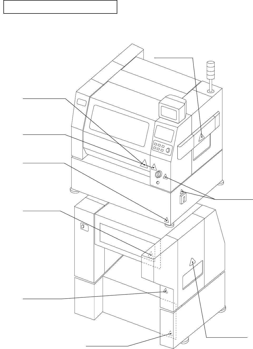
Where to stick warning labels
[Front]
[Rear]
Moving parts
warning label
"Take care not to be
caught in the machine"
warning label
Moving parts
warning label
"Take care not to be
caught in the machine"
warning label
High voltage
warning labels
High voltage
warning labels
Moving parts
warning label
High voltage
warning labels
Moving parts
warning label
VI
Matters of Caution for Safe Use of
KE-2010M/KE-2010L/KE-2010E
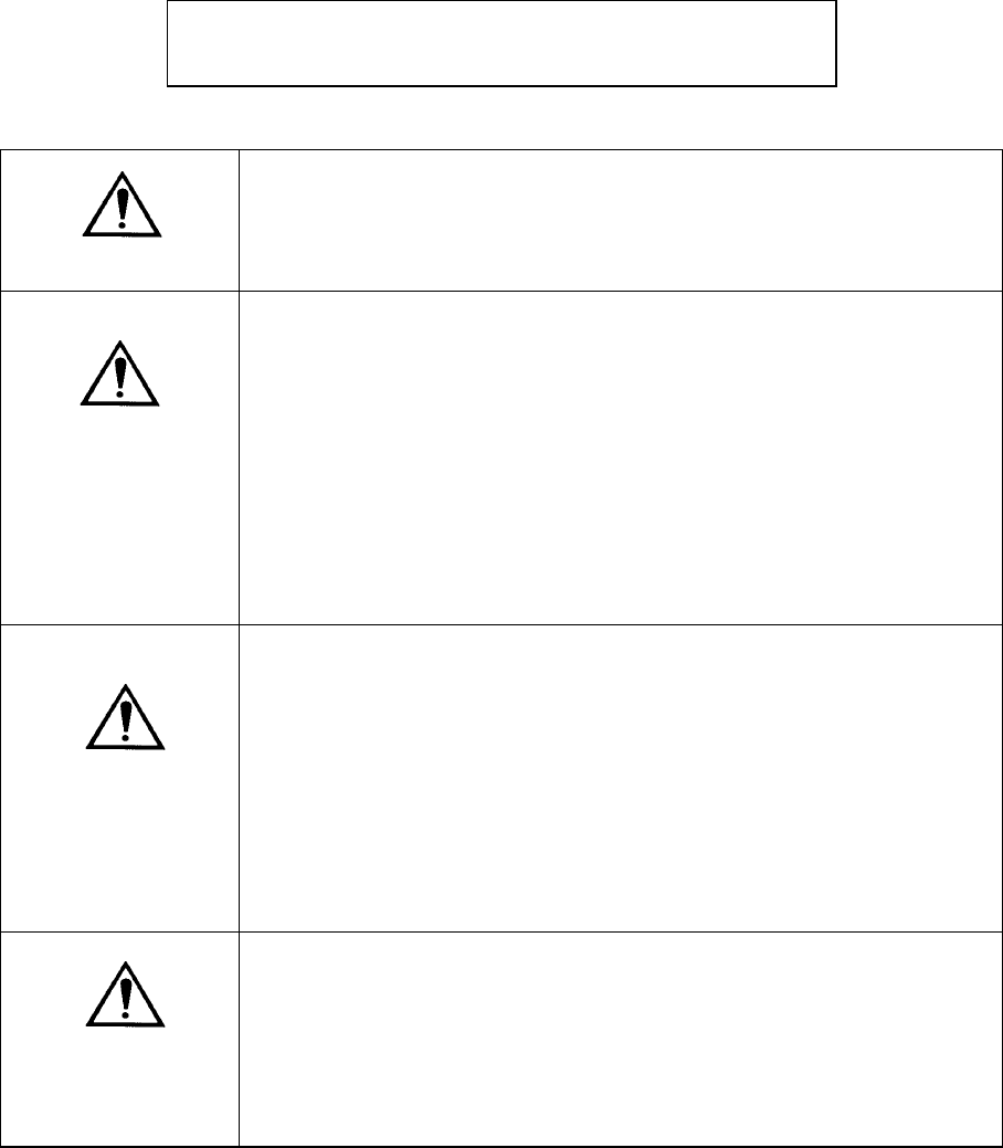
DANGER
1. To prevent accidents due to electric shock, do not open the
electrical equipment box while power supply is on.
2. To prevent electric shock, do not operate the machine, with the
grounding line unlinked.
CAUTION
1.
To prevent damage to human bodies, do not operate the
machine, with the safety cover or equipment removed.
2.
To prevent damage to human bodies, make sure that hair,
clothes, etc., will not be caught by the conveyor chain. Also,
keep off gloves.
3.
To prevent damage to human bodies, turn off power supply
during maintenance (greasing, adjustment, and daily
inspection).
4.
To prevent damage to human bodies, use an earth leakage
breaker for the power line.
CAUTION
1.
Windows NT (including the Ethernet communication function) is
adopted as the Operating System of this machine.
If you install on this machine any software not designed for this
machine, we cannot guarantee that the machine functions
properly. if you move, rename or copy a file stored in the
hard disk drive, we cannot guarantee that either.
•
Should the machine not properly due to any operation above,
replace your hard disk drive with new one and your data may
be lost.
CAUTION
1.
A UPS is incorporated into this machine to protect a production
program and any other data at power failure.
To prevent a battery built into the UPS from degrading, do not
leave this machine without turning it on for six months or longer.
•
Only when the main circuit breaker and main switch are set
to ON, this machine is assumed to be turned on.
1 − 1
CHAPTER 1 GENERAL
1.1 Highlights and Specifications
This machine is an SMD chip shooter designed as one of the KE-2000 series products
which are successors of the KE-700 series chip placers, and features high-speed chip
placement.
A host line computer (HLC) controls a line consisting the KE-2000 series chip
placer/shooter, KE-700 series chip placer, JUKI dispenser and solder-paste printer as
well as a line consisting of KE-2000 series chip placers/shooters only. This feature
allows you to configure a line which realizes high productivity and is appropriate for
every applications.
For software, WindowsNT is adopted as the Operating System (OS) to increase the
operability of this machine.
1.1.1 Highlights
– Equipped with two sets of the newly developed laser alignment sensors (MNLA)
each of which allows four nozzles to recognize components simultaneously, and
controls the nozzles in the X direction independently. In addition, equipped with
two placement stations for transferring a board simultaneously to enable
simultaneous pick-up and placement of components by driving one of these
placement stations in the Y direction.
– Simultaneous pick-up and placement of components with two heads (total eight
nozzles) enables high-speed placement of components on the almost entire area
of a 330 mm x 250 mm board: 20,000 cph (rough estimate calculated on the
assumption that eight components are simultaneously picked up and two
components are simultaneously placed).
– An offset correction camera, a height measurement device (option), and a feeder
preparation function (option) can be installed to minimize the time required for the
machine halt for preparation, realizing high operating ratio.
– Each position offset camera attached on both of two heads uses its pattern
matching function to recognize a fiducial mark at high speed. Together with
high-speed board transfer, it provides you with an overall high-speed placement
capability.
– Pick and placement reliability is remarkably improved through chip rise detection
performed during laser/align measurement.
– The board support section (for backing up a board) is driven by a motor to prevent
any vibration from occurring when a clamped board is released, then prevent a
placed component from being shifted from the regulated position, shortening the
time required to clamp or release a board.
– Using the offset correction camera and the height measurement device,
preparation is possible without opening the cover, provided as good safety
features.
– Newly attached LED indicators (optional) (Feeder Position Indicator: FPI) on the
feeder setting section notify an operator that components run out, and generates
the warning on the number of the remaining components to increase the
operability for replacing components.