Host Computer System.pdf - 第13页
AVK3 HOST COMPUTER SYSTEM 1.1 RS- 232C D77HEC-51- 010-A1 1.1- 4 Si nce the DR (Data set ready) signal means the ot her interfac e termi na l side is ready, i t checks onl y if “O N” at the start up process of charac ter …
AVK3
HOST COMPUTER SYSTEM
1.1 RS-232C
D77HEC-51-010-A1
1.1-3
Control Code
In the transmission unit, ASCII code with parity is used. The following is the chart of ASCII code.
b6 →
0 0 0 0 1 1 1 1
b5 →
0 0 1 1 0 0 1 1
b4 →
0 1 0 1 0 1 0 1
Hex-
adec-
imal
0 1 2 3 4 5 6 7
Bit
(7 bit)
bbbb
3210
↓↓↓↓
Hexadeci-
mal
0000 0 NUL DLE SP 0 @ P ‘ p
0001 1 SOH DC1 ! 1 A Q a q
0010 2 STX DC2 ” 2 B R b r
0011 3 ETX DC3 # 3 C S c s
0100 4 EOT DC4 $ 4 D T d t
0101 5 ENQ NAK % 5 E U e u
0110 6 ACK SYN & 6 F V f v
0111 7 BEL ETB ’ 7 G W g w
1000 8 BS CAN ( 8 H X h x
1001 9 HT EN ) 9 I Y i y
1010 A LF SUB
∗
: J Z j z
1011 B VT ESC + ; K [ k {
1100 C FF FS , < L l !
1101 D CR GS - = M ] m }
1110 E SO RS
⋅
> N ^ n ~
1111 F SI US / ? O _ o DEL
1.1.5 Basic Transmission Timing of Transmission Unit
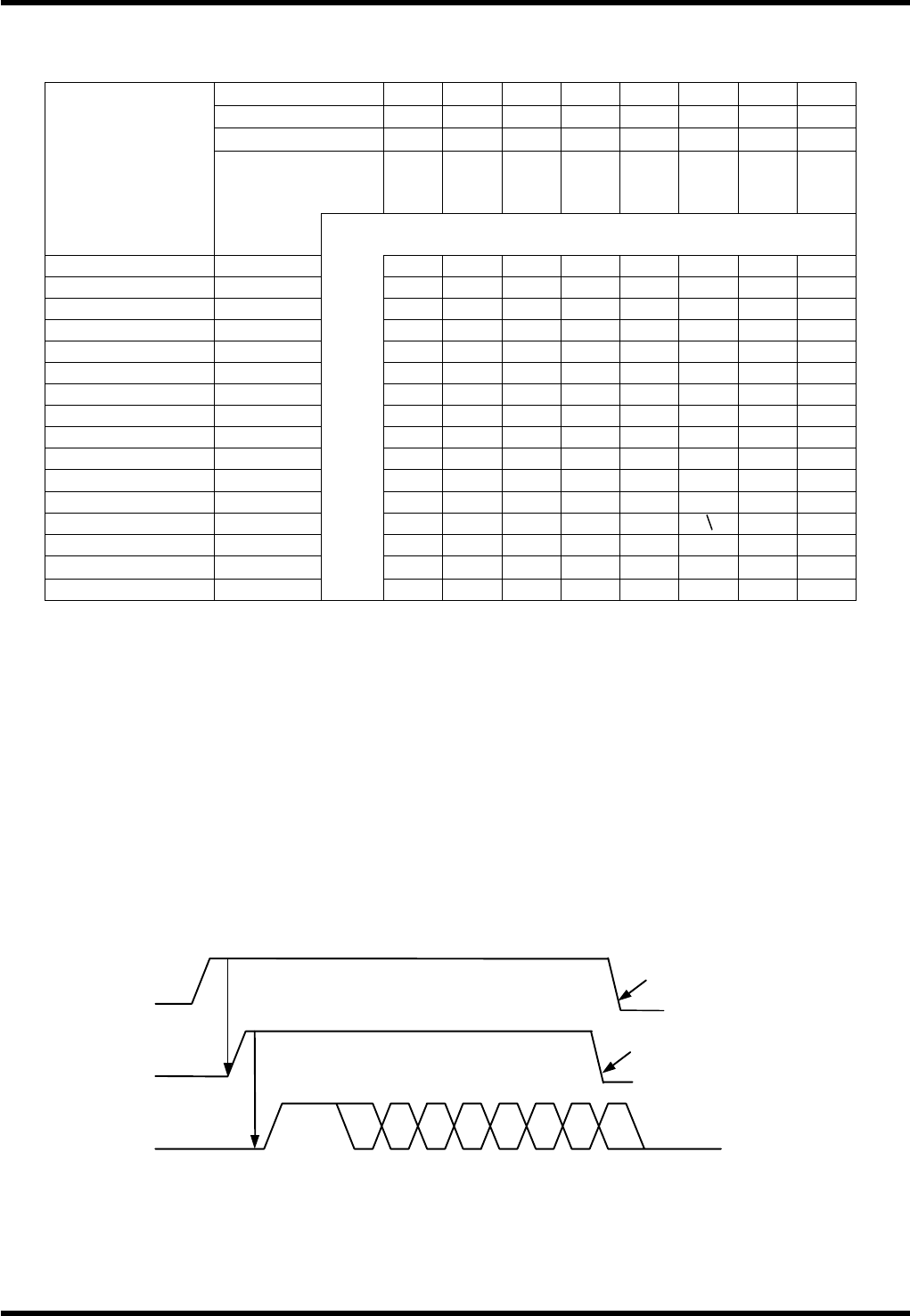
One character basic transmission timing of AVK3 is as shown below.
ER signal (Terminal ready signal) is set by the initial process when power is turned on, and can be reset
simply by the emergency stop switch.
1) Character sending timing
When the request to send signal (RS) is output to the other interface side, the clear to send the signal
(CS) will come back from the other side. Then, characters are automatically sent from AVK3.
The CS signal is called “clear to send”, and if the other side is in a receiving mode, the characters are
always output, especially if the other side has a hardware buffer of a certain degree.
RS (Output)
S 0 1 3245P6S
Turns ON the request to send signal.
Clear to send signal returns.
When status TXE turns “ON”
RS output turns “OFF”.
When receiving process starts, RS
output turns “OFF”.
CS (Input)
SD (Output)

AVK3
HOST COMPUTER SYSTEM
1.1 RS-232C
D77HEC-51-010-A1
1.1-4
Since the DR (Data set ready) signal means the other interface terminal side is ready, it checks only if
“ON” at the startup process of character sending. If DR signal is “OFF”, character sending waits until it
is turned “ON”.
2) Character receiving timing
For receiving characters there are not restrictions or conditions in communications, so all characters
output by the Host computer can be read. However, the characters received when processing the
received command are neglected.
1.1.6 Changing Data Transmission Mode
Because the control of RS-232C interface varies with the type of host computer, the machine is equipped
with mode changeover switches.
1) Optional break character function
In some cases, inputting of break character may cause inconvenience. In this case, turn the
changeover SW ON and the outputting of the break character from the AVK3 becomes ineffective.
2) Optional check sum function
The data transmission format includes check sum data. Even if the results of this check sum data
accumulation are in error, it is okay with this changeover switch. Check sum data is necessary to
comply with format, so do not forget to add dummy figures.
3) R commands
If a host computer is used for only NC data transmission, there may be trouble whenever real time
information is input to the host computer. If the changeover switch is ON, all R commands from AVK3
will be blocked.
4) Momentary selection of M and T commands at the time of NC data output
When the NC data in AVK3 is output to the host computer by C1 command, normally, even if M and T
commands are the same, the respective blocks are output similarity as in T1M1. This results in
increased time for data transmission. Therefore, when M and T commands are the same, the
command part can be out and it is this changeover switch that shortens the data.
5) Optional time-out processing
Turn ON changeover switch when you do not want time out processing.
6) End code selection
Turn the changeover switch to CR when using CR code for ETX as the message end code.
AVK3
HOST COMPUTER SYSTEM
1.2 PanaProtocol and Command Specifications
D77HEC-51-020-A0
1.2-1
1.2. PanaProtocol and Command Specifications
D77HEC-51-020-A0
1.2.1 Message Format
The machine and the host computer are connected by RS-232C interface as hardware. And, as software, in
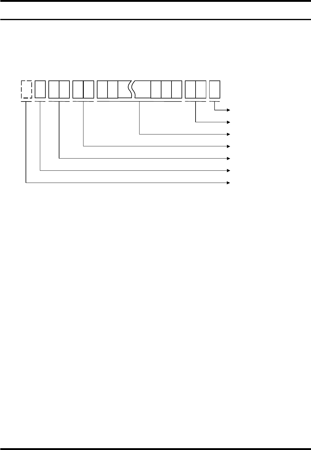
byte unit, ASCII code (with parity) is used. The message format is as follows, and STX code to ETX code is
processed as one message. It includes number of characters, command, data and check sum data.
STX (START OF TEXT)
The character STX which appears first until the ETX which appears next are processed as one
message. The STX which appears in the message again is processed only as one unit of data. The
ASCII code with parity is H'82.
Number of characters
The number of characters in the command and data fields is counted in binary, and the result of 8 bits
are divided into 4 bits each of upper and lower digits. They are respectively expressed in hexadecimals
(X0” - F”) and processed by ASCII code.
Since hexadecimals are 2 digits, the largest number is FF (256). To read this much data, 256 codes for
256 buffers are required for the interface in the AVK3.
In actual practice, however, 36 codes can meet requirements for all commands according to the
command contents described later. As a result, the maximum number of codes to be received in one
message by the machine is 96 characters including margin. However, even when characters other
than those specified by commands are included in data, they are stored in the buffer when the machine
receives the data. So be careful not to overflow the capacity when the label is added by the user.
In this case, attention must also be paid since characters other than those specified should also be
counted.
C 1 D 0 5 EN 1 1Z 2
EXT: 1 digit
Check sum: 1 digit
Data field: Max. 88 digits
Command field: 2 digits
No. of characters: 2 digits
(
Command + data)
STX: 1 digit
Break code
(Optional)