Host Computer System.pdf - 第161页
AVK3 HOST COMPUTER SYSTEM 6.2 R Comm ands: R0,R1, R2,R3 D77HEC-55- 020-A0 6.2- 4 11. RC Thi s occurs when inserti on error occurs or cor recti on st art fr o m C5T RC co mm and or from cont rol panel begins. 12. LD Thi s…
AVK3
HOST COMPUTER SYSTEM
6.2 R Commands: R0,R1,R2,R3
D77HEC-55-020-A0
6.2-3
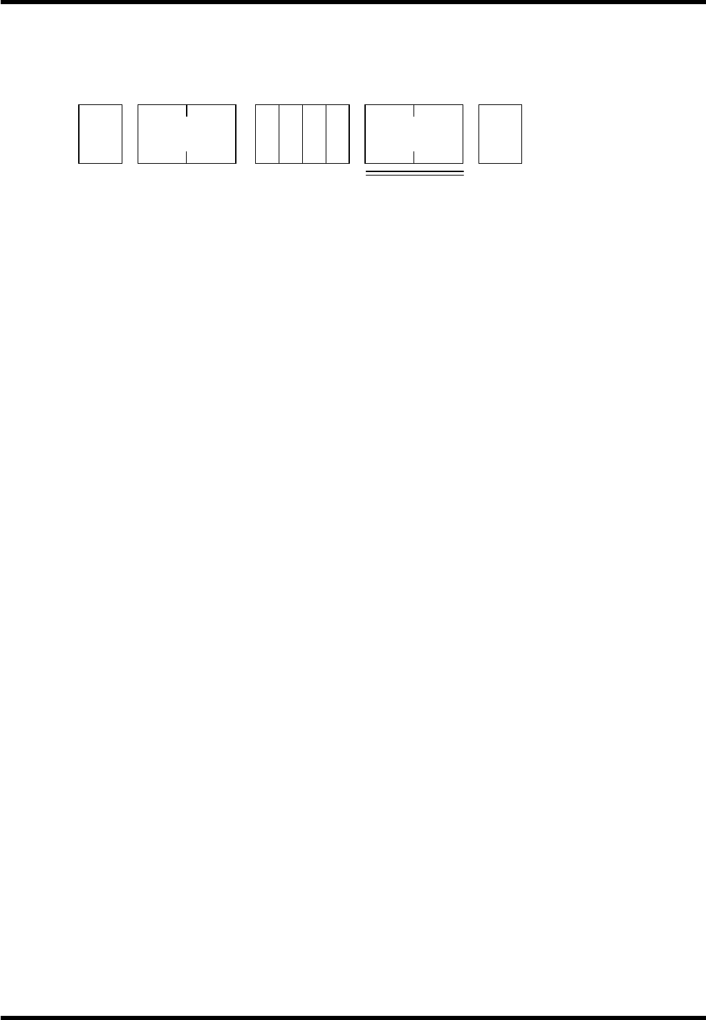
6.2.2 Operation mode information: R1
The R1 command is to let the host computer know when an operator or host computer is positively operating
the control switches on the AVK3.
Data details
2.
1. OL or FL
These commands inform the host computer that the control mode of AVK3 is the online (OL) or off-line
(FL). This is generated when mode select switch on the main control panel of AVK3 is switched over,
or immediately after the power is turned ON.
2. ES
When the power is shut down by an emergency stop, R1ES command is outputted by the contact input
of ES switch.
3. ST
This command informs the host computer that AVK3 has started because the START switch on the
main control panel was pressed or a C5ST command was input from the host computer. This is the
signal output when AVK3 has started operation. This signal is also output at the time of restart.
4. SP
This command shows that AVK3 has stopped in conditions other than error.
Actually, it is the normal stopping of 1. Block operation other than at the final print block.
When the NC program switch is “EOP”, this command is not sent and R0EP command is output to
distinguish from stop in EOP stop mode.
5. PS
When a PCB is transferred to the start of the loader rail, the PCB detector 2LS goes ON. When this
switch goes ON (when the PCB is correctly set on the loader rail), this command is output. When
inputting a C5ST start to the AVK3, It is necessary to check that this R1PS command has been
previously input to the host computer.
6. RE
When the “OPERATION RESET” switch on the main control panel has been pressed by the operator
or the C5RE command has been executed by the host computer.
7. PW
In the NC program when G1T4 command is executed, X-Y-Z axes return to origin point and PCB
loading is conducted on X-Y table. At this time, if there is no PCB at the head of the loader rail (that is,
if R1PS command has not occurred prior to it), it is in the PCB arrival waiting condition. In such
conditions, this command occurs.
This signal also occurs when it is impossible to convey away the PCB on the loader rail because the
unloader stocker is full, and PCB loading is impossible.
8. PE
This command shows that the above-mentioned R1PW command condition has been eliminated.
That is, after R1PW has occurred, this command occurs when PCB arrived at head of loader rail, or
when PCB has been discharged to unloader.
9. OC
This is the command informing the host computer that the XY axes started origin return action and
completed the action through inputting C5UP command (PCB sweep out command) from the host
computer.
10. UP
Sweeps out PCB in XY tables through inputting C5UP command from host computer. This is the
command informing the host computer of the C5UP action completion when PCB sweep out was
completed.
STX
No. of
characters
R 1
ETX
1 to 21
* *
Check sum
AVK3
HOST COMPUTER SYSTEM
6.2 R Commands: R0,R1,R2,R3
D77HEC-55-020-A0
6.2-4
11. RC
This occurs when insertion error occurs or correction start from C5TRC command or from control panel
begins.
12. LD
This command is sent when the loading operation has been completed.
13. LE
This command occurs, with the magazine stocker connected to the loader side, when PCB become
unable of being fed because of the rack being empty.
14. LF
This command occurs, with the magazine stocker connected to the loader side, when the empty racks
already finished supplying the PCB are fully stocked and the following rack cannot be set.
15. LS
This command occurs, with the magazine stoker connected to the loader side, when PCB in the rack
have all been supplied and the following rack setting completes at the PCB supply position.
16. LO
This command occurs. In the condition above, when the empty rack already finished supplying all the
PCB is swept out.
17. UE
This command occurs, with the magazine stocker connected to the unloader side, when the empty
racks to contain PCB runs out, thus the PCB become unable of being fed.
18. UF
This command occurs, with the magazine stocker connected to the unloader side, when the racks
finished stocking the PCB became full and the following rack cannot be set (unable stock PCB).
19. US
This command occurs, with the magazine stocker connected to the unloader side, when the empty
rack is set at the PCB containing position.
20. UO
This command occurs, with the magazine stocker connected to the unloader side, when the rack fully
containing the PCB and the rack is swept out to the unloading position.
21. TE
This command is sent when width adjustment has been completed normally.
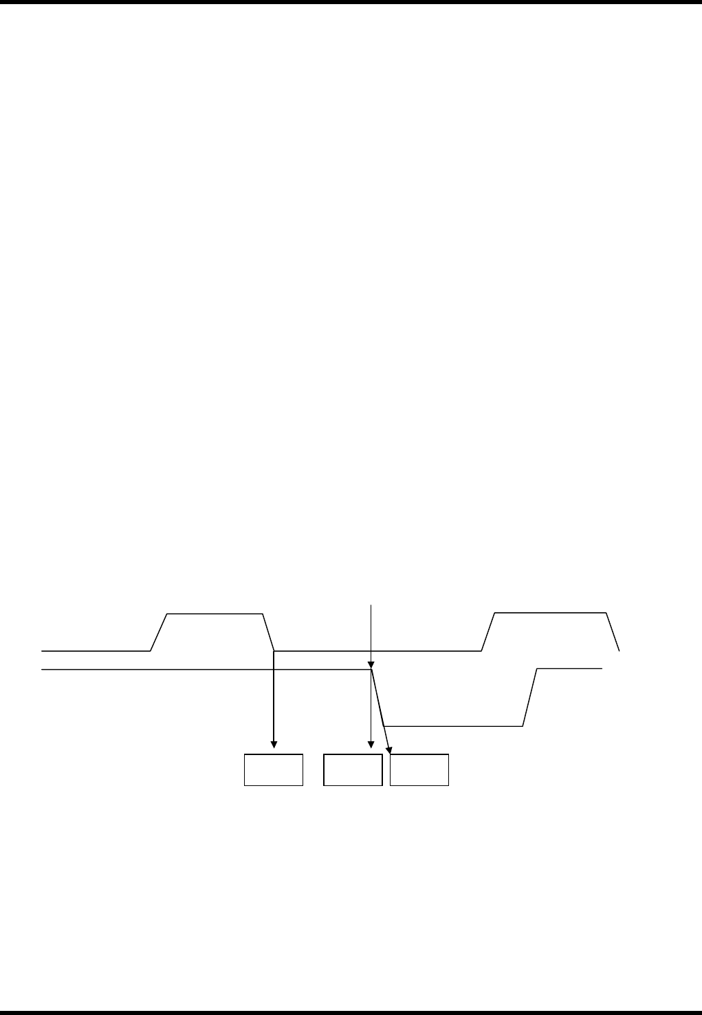
Command output example
PCB arrival waiting
XY table
Loader operation
R1PS
R1PER1PW
Origin return
operation
PCB arrives at head of loader rail
PCB
loading
AVK3
HOST COMPUTER SYSTEM
6.2 R Commands: R0,R1,R2,R3
D77HEC-55-020-A0
6.2-5
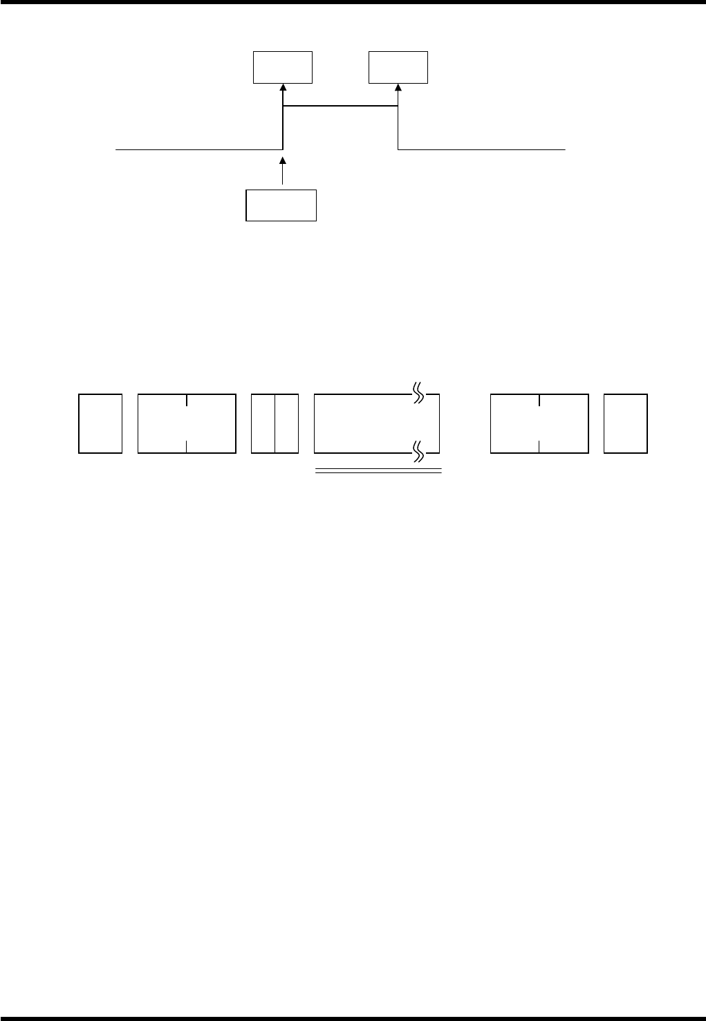
1 BLOCK start command
Condition
Valid in ONLINE mode only in the commands except for R1FL and R1ES.
6.2.3 Machine Error Information: R2
There are many error detections while AVK3 is in operation, and they have the function of stopping AVK3
automatically.
This R2 command is to inform the host computer of these errors.
Data details
In the error information, a 3-digit block number (N) is added as follows:
NC data block number (N: 3 digits), parts feeder number (Z: 3 digits), M command (3 digits) and T command
(3 digits) are added to error information.
Data code part is applicable as the following. (x represents numbers 0- 9.)
Data codes
3.
1. E01 (Sxxx) NxxxZxxxMxxxTxxx
This is an error information showing that the insertion error occurred and the machine made a stop.
Data thereafter E01 is the NC data that the insertion error has occurred.
2. E02 (Sxxx) NxxxZxxxMxxxTxxx
This is an error information showing that the anvil short occurred and the machine made a stop.
3. E03 (Sxxx) NxxxZxxxMxxxTxxx
This is an error information showing that parts exhaustion error occurred and the machine made a
stop.
Z number represents the parts empty feeder number.
4. E04 (Sxxx) NxxxZxxxMxxxTxxx
This is an error information showing that the PCB guide error occurred and the machine made a stop.
5. E05 (Sxxx) NxxxZxxxMxxxTxxx
This is an error information showing that the error occurred regarding the PCB loading onto XY table
(such as carry error, positioner error).
6. E06 (Sxxx) NxxxZxxxMxxxTxxx
This is an error information showing that the cut mistake error occurred on axial parts and the
machine made a stop.
(The information is not used for the current AVK3 model.)
7. E07 (Sxxx) NxxxZxxxMxxxTxxx <X, Y, ZL, ZR, WH, WA, V>
This is an overrun information generated when any axis runs over the + limit.
The letter <> indicates the axes which run over the limits to stop.
AVK3
<1BLOCK operation>
C5STBL
1 BLOCK start command
The AVK3 stops automatically
R1ST
R1SP
STX
R 2 Data code
No. of
characters
1 to 11
Check sum ETX