00193922-01.pdf - 第103页
User Manual SIPLAC E HF Series 3 Technical data Software Vers ion SR.505.xx 05/2004 US Edition 3.6 Placem ent heads 103 3.6.3 6-segment Collec t&Place he ad for high-spe ed IC pl acement 3 Fig. 3.6 - 6 6-segment Coll…
3 Technical data User Manual SIPLACE HF Series
3.6 Placement heads Software Version SR.505.xx 05/2004 US Edition
102
nozzle are constantly checked throughout the entire pick-up and placement process in order to
keep the placement error rate as low as possible.
3.6.2.3 Technical data
3
12-segment Collect&Place head
with standard component vision
camera
12-segment Collect&Place
head with DCA camera
Range of components 0201 to PLCC44, BGA, µBGA,
flip-chip, TSOP, QFP, SO to
SO32, DRAM
0201 to flip-chip, bare die
Component specification
Max. height
Min. lead pitch
Min. bump pitch
Min. ball bump ∅
Min. dimensions
Max. dimensions
Max. weight
6 mm
0.5 mm
0.35 mm
0.2 mm
0.6 x 0.3 mm²
18.7 x 18.7 mm²
2 g
6 mm
0.4 mm
0.2 mm
0.11 mm
0.6 x 0.3 mm²
13 x 13 mm²
2 g
Programmable set-down
force
2.4 N - 5.0 N 2.4 N - 5.0 N
Nozzle types 9 xx 9 xx
X/Y accuracy ± 60 µm/4 σ ± 55 µm/4 σ
Angular accuracy ± 0.7°/4 σ ± 0.7°/4 σ
User Manual SIPLACE HF Series 3 Technical data
Software Version SR.505.xx 05/2004 US Edition 3.6 Placement heads
103
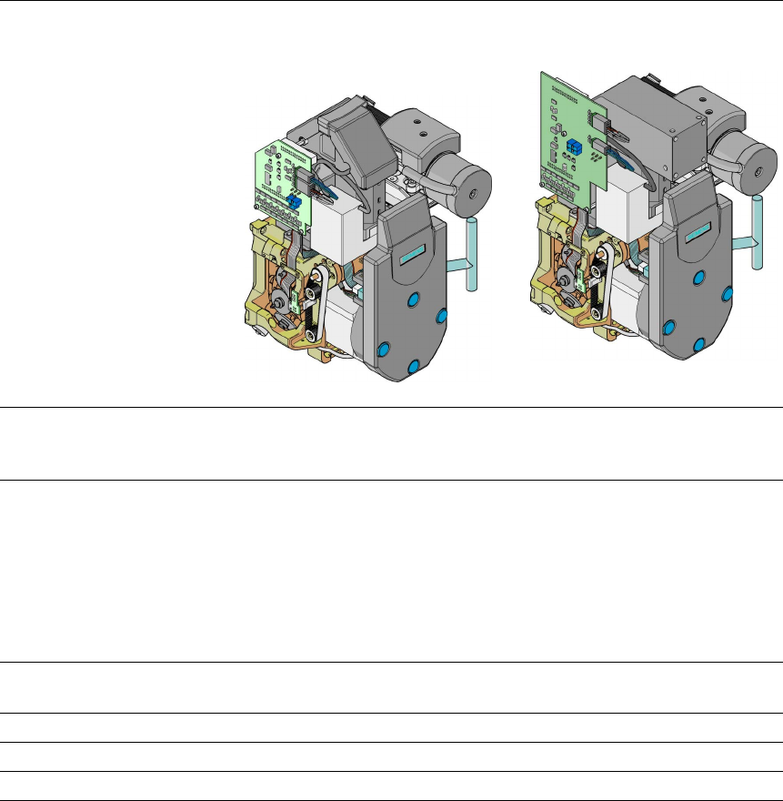
3.6.3 6-segment Collect&Place head for high-speed IC placement
3
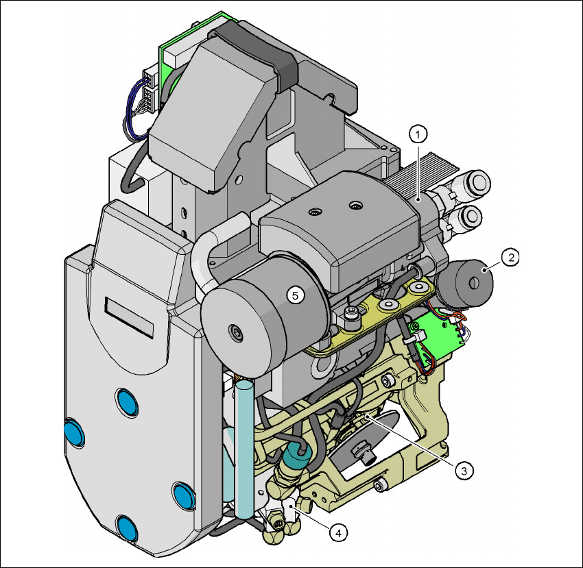
Fig. 3.6 - 6 6-segment Collect&Place head - Function groups, part 1
3
(1)Vacuum generator
(2)Turning station, DP axis
(3)Star with 6 sleeves - star axis
(4)Forced air valve
(5)Silencer
3 Technical data User Manual SIPLACE HF Series
3.6 Placement heads Software Version SR.505.xx 05/2004 US Edition
104
3
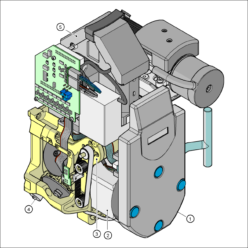
Fig. 3.6 - 7 6-segment Collect&Place head - Function groups, part 2
3
(1) Intermediate distributor board, beneath the cover
(2) Star drive - DR motor
(3) Z axis motor
(4) Valve adjustment drive
(5)39 x 39 component vision camera