00193922-01.pdf - 第112页
3 Technical data User Manual SIPLACE HF Series 3.7 Electrical and pneumat ic connection points S oftware Version SR.505.xx 05/2004 US Edition 112 3.7 Electrical and pneum a tic connection point s 3.7.1 Electrical connect…
User Manual SIPLACE HF Series 3 Technical data
Software Version SR.505.xx 05/2004 US Edition 3.6 Placement heads
111
3.6.4.3 Technical data
3
3
* A special nozzle is needed for forces < 1 N. 3
Optical centering with Stationary P&P component
vision camera (type 22) 50 x 40
Stationary P&P component
vision camera (type 20) 8 x 8
Range of components 0603 to SO, PLCC, QFP, BGA,
special components, bare dies,
flip-chips
0201 to SO, PLCC, QFP, sock-
ets, plugs, BGA, special compo-
nents, bare dies, flip-chips,
shields
Component specification
max. height
min. lead pitch
min. bump pitch
min. ball bump ∅
min. dimensions
max. dimensions
max. weight
25 mm (higher available upon
request)
0.4 mm
0.56 mm
0.32 mm
1.6 x 0.8 mm²
50 x 40 mm²
(single measurement)
For use with two nozzles
50 x 50 mm² or
69 x 10 mm²
For use with one nozzle:
85 x 85 mm² or
125 x 10 mm²
max. 200 x 125 mm² (with
restrictions)
100 g
25 mm (higher available upon
request)
0.25 mm
0.14 mm
0.08 mm
0.6 x 0.3 mm²
8 x 8 mm²
(single measurement)
100 g
Programmable set-down
force
0.5 N - 15 N
*
0.5 N - 15 N
*
Nozzle types 5 xx (standard)
4 xx + adapter
8 xx + adapter
9 xx + adapter
5 xx (standard)
4 xx + adapter
8 xx + adapter
9 xx + adapter
Nozzle spacing on the
two Pick&Place heads
70.8 mm 70.8 mm
X/Y accuracy ± 35 µm/4 σ ± 30 µm/4 σ
Angular accuracy 0.07° / 4 σ 0.07° / 4 σ
3 Technical data User Manual SIPLACE HF Series
3.7 Electrical and pneumatic connection points Software Version SR.505.xx 05/2004 US Edition
112
3.7 Electrical and pneumatic connection points
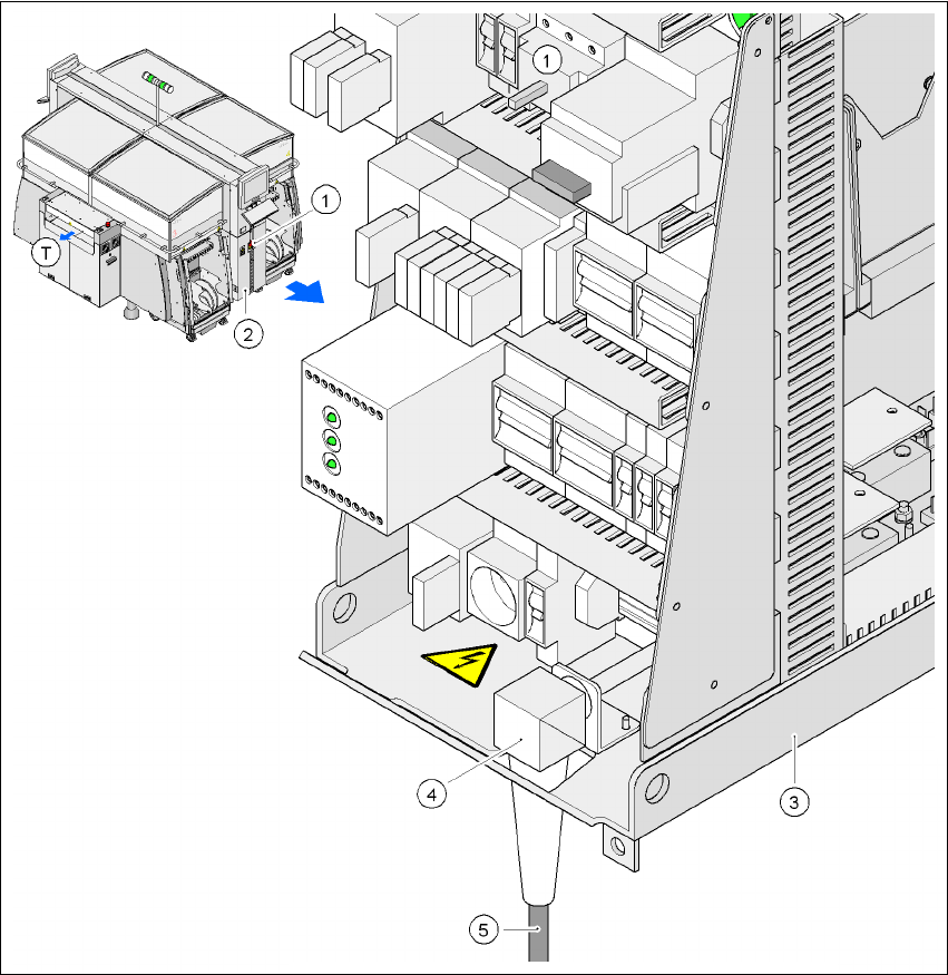
3.7.1 Electrical connection points
3
Fig. 3.7 - 1 Electrical connection points on the placement machine
3
(1) Main power switch
(2) Cover over the power supply unit
(3) Power supply unit
(4) Angle for the cable gland
(5) Power cable
(T)Direction of PCB transport
User Manual SIPLACE HF Series 3 Technical data
Software Version SR.505.xx 05/2004 US Edition 3.7 Electrical and pneumatic connection points
113
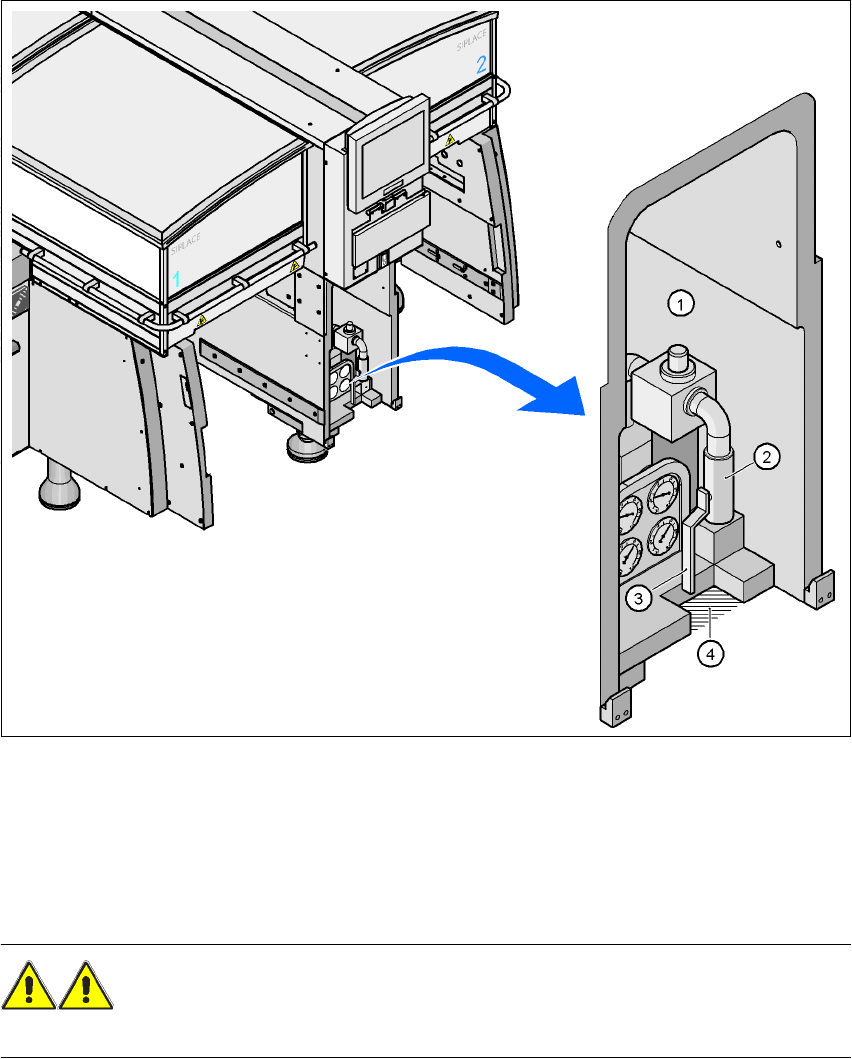
3.7.2 Pneumatic connection point
Fig. 3.7 - 2 Pneumatic connection point on the placement machine
3
(1)Pneumatic unit
(2)Coupling for connecting the compressed air hose
(3)Stop valve
(4)Recess for the air hose
WARNING
NEVER detach compressed air lines while they are still pressurized. Risk of injury. 3