00193922-01.pdf - 第119页
User Manual SIPLAC E HF Series 3 Technical data Software Vers ion SR.505.xx 05/2004 US Edition 3.8 Dimensions and weight of the placement m achine 119 3.8.7 Dimensions of the HF placem ent system with matri x tray change…
3 Technical data User Manual SIPLACE HF Series
3.8 Dimensions and weight of the placement machine Software Version SR.505.xx 05/2004 US Edition
118
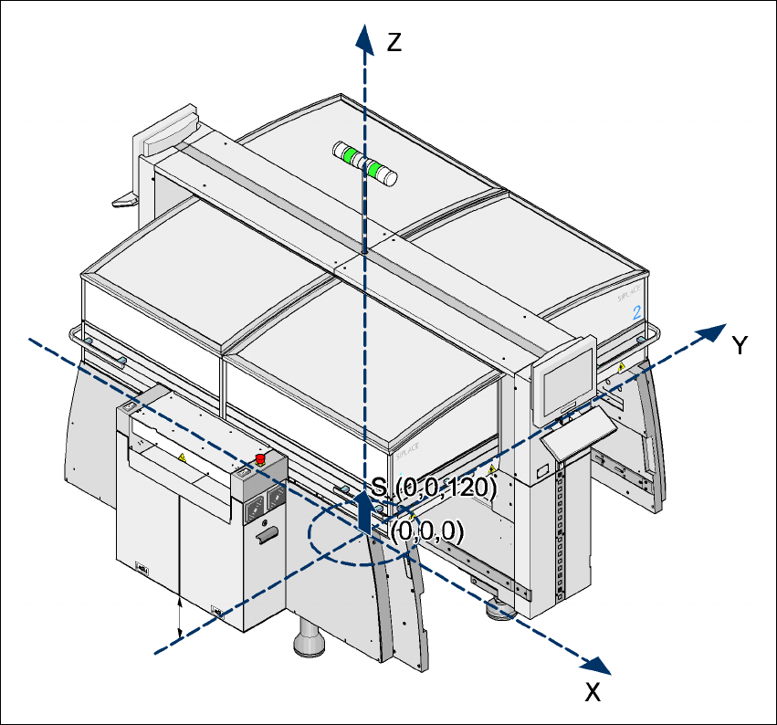
3.8.6 Center of gravity for the HF and the HF/3 placement machines
3
3
3
3
Fig. 3.8 - 4 Center of gravity for the HF and the HF/3 placement machines in millimeters
3
X coordinate 0 mm
Y coordinate 0 mm
Z coordinate 120 mm high
T PCB transport direction
These center of gravity coordinates relate to placement systems with a PCB transport height of
830 mm.
User Manual SIPLACE HF Series 3 Technical data
Software Version SR.505.xx 05/2004 US Edition 3.8 Dimensions and weight of the placement machine
119
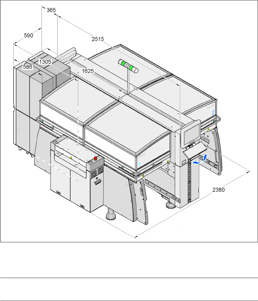
3.8.7 Dimensions of the HF placement system with matrix tray changer
3
3
3
3
Fig. 3.8 - 5 Dimensions of the HF placement system with matrix tray changer in millimeters
3
NOTE 3
A matrix tray changer may be docked in at locations 2 and 4 in place of a component trolley.
3 Technical data User Manual SIPLACE HF Series
3.8 Dimensions and weight of the placement machine Software Version SR.505.xx 05/2004 US Edition
120
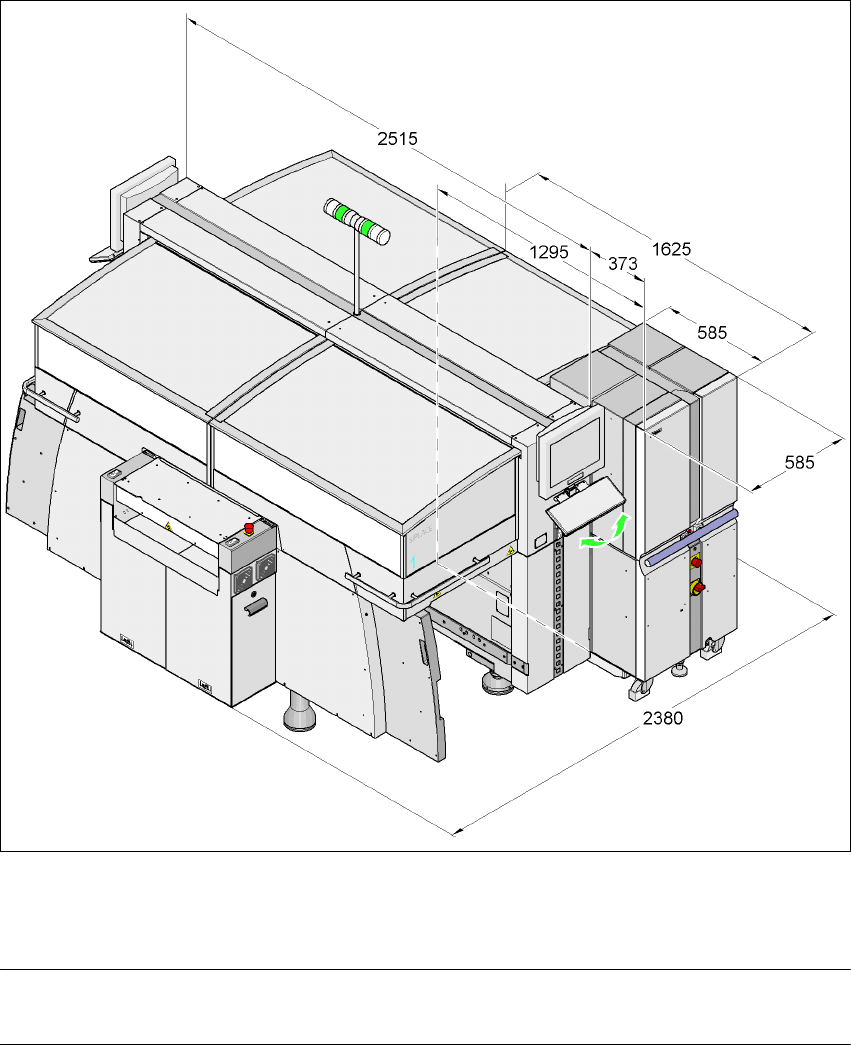
3.8.8 Dimensions of the HF/3 placement system with matrix tray changer
3
3
3
3
Fig. 3.8 - 6 Dimensions of the HF /3 placement system with matrix tray changer in millimeters
3
NOTE 3
The matrix tray changer can only be docked in at location 2.