00193922-01.pdf - 第122页
3 Technical data User Manual SIPLACE HF Series 3.9 Controls Software Version S R.505.xx 05/2004 US E dition 122 3.9 Controls 3.9.1 Controls and displays 3 Fig. 3.9 - 1 Controls and displays 3 (1)Ope rator panel on the po…
User Manual SIPLACE HF Series 3 Technical data
Software Version SR.505.xx 05/2004 US Edition 3.8 Dimensions and weight of the placement machine
121
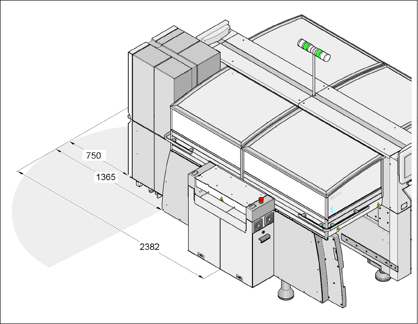
3.8.9 Maneuvering radius of the matrix tray changer
3
3
3
3
Fig. 3.8 - 7 Maneuvering radius of the MTC
3
HF placement machine: Locations 2 and 4 3
HF/3 placement machine: Location 2 only 3
3 Technical data User Manual SIPLACE HF Series
3.9 Controls Software Version SR.505.xx 05/2004 US Edition
122
3.9 Controls
3.9.1 Controls and displays
3
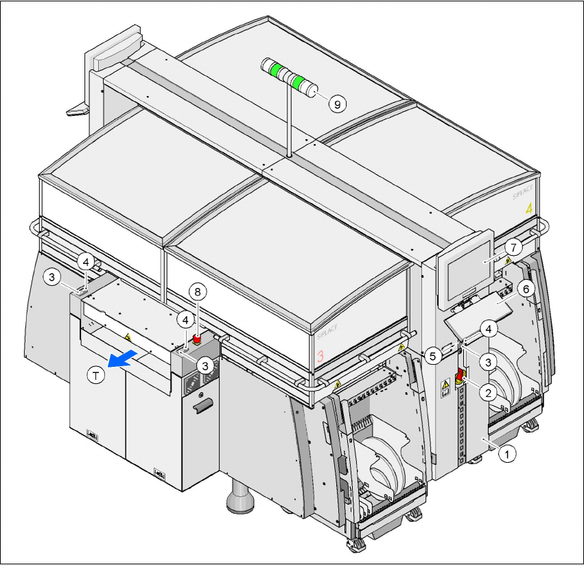
Fig. 3.9 - 1 Controls and displays
3
(1)Operator panel on the power supply side (2)Main power switch
(3) Stop button (black) (4)Start button (white)
(5) Component counter (6)Keyboard
(7) LCD touchscreen (8)Emergency stop button
(9) Indicator lamps (T)Direction of PCB transport
User Manual SIPLACE HF Series 3 Technical data
Software Version SR.505.xx 05/2004 US Edition 3.9 Controls
123
3.9.2 Description
All the controls can be reached by a 1.60 m tall person. 3
Main power switch 3
The main power switch is used to switch the power supply to the placement machine on and off.3
WARNING
Some parts inside the placement machine carry potentially lethal voltages - even when switched
off at the main power switch. 3
Stop button 3
This button is used to stop the placement machine. 3
Start button 3
This button starts the placement machine after it has been switched on or after faults have been
eliminated. 3
Emergency stop button 3
The emergency stop button latches in the ON position when pressed. The power supply to the
gantry axes, the component trolleys, conveyors and used tape cutters is interrupted and the volt-
age supplied to the star axes of the placement heads is reduced. Turn the button to release it. 3
Component counter 3
The component counter displays the number of components processed. 3
LCD touchscreen 3
There is a flat LCD screen with a touch-sensitive surface (touchscreen) on either side of the place-
ment machine. The screen resolution is 1024 x 768 pixels. The screen is mounted on a frame. It
can be pulled out and placed at an angle. 3
Keyboard 3
The fold-down keyboard is located beneath the monitor. 3
Indicator lamps 3
The sequence of colors is white - green - white. These lamps are used to signal operating statuses
and malfunctions of the placement machine. 3