00193922-01.pdf - 第125页
User Manual SIPLAC E HF Series 3 Technical data Software Version SR.505.xx 05/2004 US Edition 3.9 Controls 125 3.9.3.1 Controls on the placement machine's ope rator p anels The two o perator panel have id entic al c…

3 Technical data User Manual SIPLACE HF Series
3.9 Controls Software Version SR.505.xx 05/2004 US Edition
124
Component barcode reader 3
On each side of the middle console there is a bracket that holds the Datalogic DL 910 component
barcode reader. The barcode reader enables the components to be set up and topped up quickly
and reliably. 3
3
3
3.9.3 Ergonomic arrangement of the controls
Figure 3.9 - 1 on page 122 provides an overview of the position of the controls. They are subdi-
vided into the following groups: 3
Operator panel on the right-hand side (pneumatic unit) of the center console with 3
– LCD touchscreen
– Keyboard with trackball
– Start button, Stop button
Operator panel on the left-hand side (power supply unit) of the center console with 3
– LCD touchscreen
– Keyboard with trackball
– Component counter
– Start button
– Stop button
– Main power switch
Input / output side of the PCB conveyor with 3
– Emergency stop buttons
– Start button, Stop button
User Manual SIPLACE HF Series 3 Technical data
Software Version SR.505.xx 05/2004 US Edition 3.9 Controls
125
3.9.3.1 Controls on the placement machine's operator panels
The two operator panel have identical control functions. 3
Monitor, keyboard, Start and Stop buttons 3
There is a monitor and a keyboard on both sides of the placement machine. They are arranged
so that any person who is at least 1.60 m tall can work comfortably and efficiently. 3
The Start and Stop buttons are located beneath the keyboard. The on-screen dialog will occasion-
ally prompt you to activate certain actions using buttons, and this arrangement will make it easier
for you both to activate and to interactively control these actions. 3
Main power switch 3
The main power switch is part of the power module. It is located on the left-hand operator panel
viewed in the direction of PCB transport. It is located here because it is only needed for servicing
and preventive maintenance work and is therefore not subject to frequent use. 3
3
3
3.9.3.2 Controls on the input and output sides of the placement machine
The controls on the input and output sides of the placement machine perform identical functions.3
Emergency stop buttons, Start and Stop buttons 3
There is an emergency stop button and two Start and Stop buttons on both the input and output
sides of the PCB conveyor. This arrangement was adopted for the emergency stop buttons be-
cause it enables them to be reached quickly and easily from any position. 3
In addition, it is important to have an unrestricted view of the placement heads and placement area
during preventive maintenance, servicing and setting up work in order to be able to check all the
operations carried out inside the machine. This particularly important during testing phases or
when starting single functions, for example. 3
3 Technical data User Manual SIPLACE HF Series
3.10 Gantries Software Version SR.505.xx 05/2004 US Edition
126
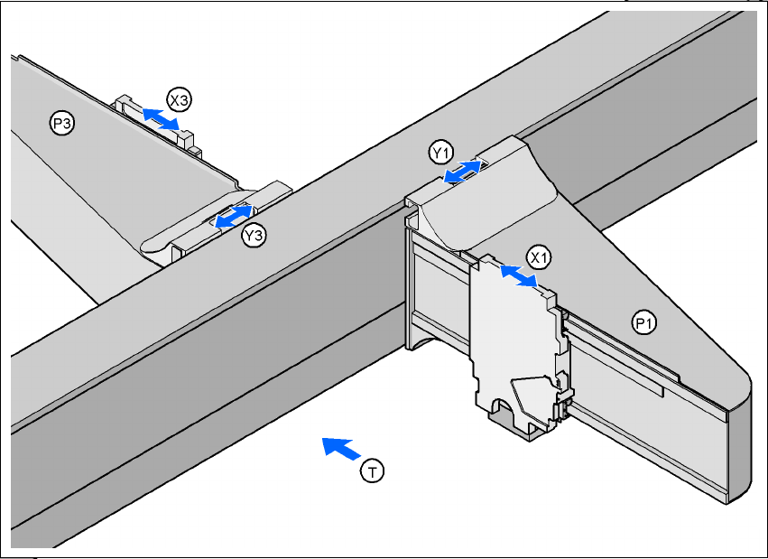
3.10 Gantries
3.10.1 Position of the gantries for the HF placement machine
3
Fig. 3.10 - 1 Position of the gantries for the HF placement machine
3
P1 Gantry 1 3
X1 X axis, gantry 1 3
Y1 Y axis, gantry 1 3
P2 Gantry 2 3
X3 X axis, gantry 3 3
Y3 Y axis, gantry 3 3
(T) Direction of PCB transport 3
3
The gantry system consists of two functional groups 3
– X axis and
–Y axis
Placement area 2
Placement area 1