00193922-01.pdf - 第132页
3 Technical data User Manual SIPLACE HF Series 3.11 Vision modules Software Version S R.505.xx 05/2004 US Edition 132 3.1 1 V ision modules Every 6-segme nt and eve ry 12-seg ment Colle ct&Place head ha s a separate …

User Manual SIPLACE HF Series 3 Technical data
Software Version SR.505.xx 05/2004 US Edition 3.10 Gantries
131
The Y axis essentially consists of the following main modules: 3
– Linear drive with permanent magnet (1)
– Guide system (2)
– Linear distance measuring system (3)
– Trailing cable (4)
3
The Y axis is driven by a linear motor. The secondary part of the drive is made up of permanent
magnets and is mounted on the machine frame. The primary part is bolted to the gantry. 3
3.10.6 Technical data for the Y axis
Drive Direct, linear motor
Maximum speed 2.5 m/sec.
Traversing path 1430 mm
Distance measuring system Metal linear scale
Scale length 1850 mm
Resolution 1 µm
3 Technical data User Manual SIPLACE HF Series
3.11 Vision modules Software Version SR.505.xx 05/2004 US Edition
132
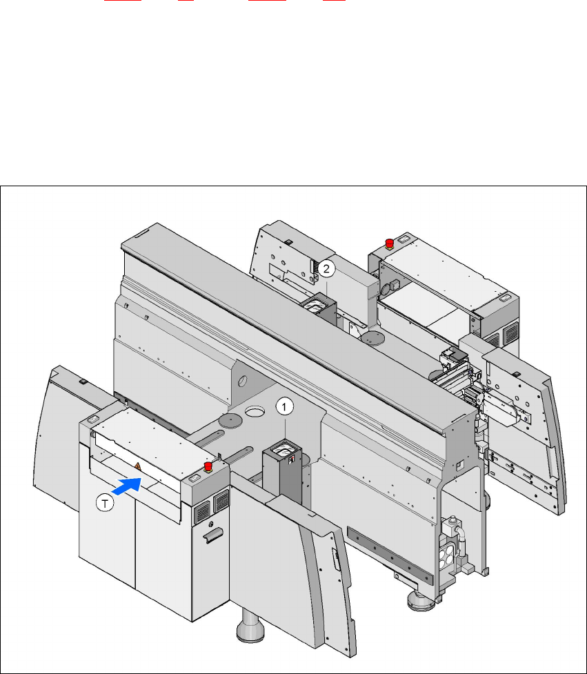
3.11 Vision modules
Every 6-segment and every 12-segment Collect&Place head has a separate component vision
module (see Fig. 3.6 - 3
page 98 and Fig. 3.6 - 6 page 103). The stationary P&P component vision
camera (type 22) 50 x 40 is permanently fixed to the machine frame. 3
Assembly positions for the stationary P&P component vision camera (type 22) 50 x 40 3
3
3
Fig. 3.11 - 1 Assembly positions for the stationary P&P component vision camera (type 22) 50 x 40
3
(1) Assembly position for location 1
(2) Assembly position for location 3
TwinHead Stationary P&P component vision camera (type 22) 50 x 40
Placement area 1 Location 1 (HF placement machine)
Placement area 2 Location 3 (HF and HF/3 placement machine)

User Manual SIPLACE HF Series 3 Technical data
Software Version SR.505.xx 05/2004 US Edition 3.11 Vision modules
133
WARNING
RISK OF HEAD CRASH 3
When the placement head is changed from the TwinHead to the Collect&Place head, the Twin-
Head's stationary component vision camera, P&P (type 22) 50 x 40, and stationary component
vision camera, P&P (type 20) 8 x 8 must be removed, otherwise the Collect&Place head will col-
lide with the camera housings.
The component vision module is used to determine: 3
– the precise position of the components at the nozzle and
– the geometry of the package form.
The PCB vision module uses fiducials on the PCBs to determine: 3
– the position of the PCB,
– its rotation angle
– and the PCB skew.
The PCB cameras are fixed to the bottom of the gantries. They use fiducials on the feeders to
determine the exact pick-up position of components, which is particularly important for small com-
ponents. 3