00193922-01.pdf - 第139页
User Manual SIPLAC E HF Series 3 Technical data Software Vers ion SR.505.xx 05/2004 US Edition 3.12 PC B conveyor 139 3.12.2 T echnical dat a – single c onveyor syst em 3 3.12.3 Description of the functions For placem en…
3 Technical data User Manual SIPLACE HF Series
3.12 PCB conveyor Software Version SR.505.xx 05/2004 US Edition
138
3.12 PCB conveyor
The placement machine is supplied with a single conveyor as standard. The dual PCB conveyor
is available as an option (see Section 7.4
, page 304). The left or the right side of the PCB conveyor
can be used as the stationary side, as required. 3
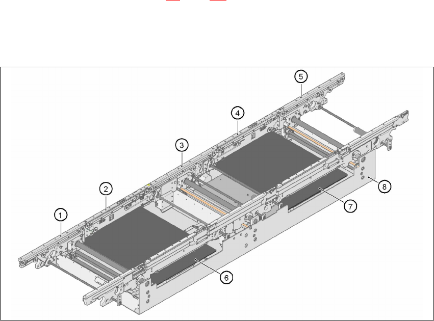
3.12.1 Structure of the PCB single conveyor
3
Fig. 3.12 - 1 Structure of the PCB single conveyor
(1) Input conveyor
(2) Processing conveyor 1
(3) Intermediate conveyor
(4) Processing conveyor 2
(5) Output conveyor
(6) Lifting table 1
(7) Lifting table 2
(8)Assembly trough

User Manual SIPLACE HF Series 3 Technical data
Software Version SR.505.xx 05/2004 US Edition 3.12 PCB conveyor
139
3.12.2 Technical data – single conveyor system
3
3.12.3 Description of the functions
For placement, the PCB is clamped from below. The distance between the top of the PCB and the
placement head thus remains unchanged for each PCB, and is no longer dependent on the thick-
ness of the PCB. The placement rate is thus also independent of the PCB thickness. The PCB
fiducial centering can also be optimized. Since the distance between the PCB surface and the
PCB camera remains the same, the PCB camera is always focussed on the PCB surface with the
same sharpness. The PCB fiducial contours are optimally mapped on the CCD chip of the PCB
camera. 3
The width of the circuit board conveyor is set and monitored by an integral control circuit. It can
be selected by calling up the program. The control circuit then actuates the stepping motors until
the desired width is reached. The width adjustment is therefore independent of other machine
components. 3
The transport height can be modified, thus allowing the machines to be integrated into lines with
a transport height of 830, 900, 930 or 950 mm. The PCB conveyors communicate with the indi-
Fixed conveyor side Right or left
PCB format
Standard (l x w)
"Long board" option
50 x 50 mm² to 450 x 508 mm²
50 x 80 mm² to 610 x 508 mm²
PCB thickness
Standard 0.3 mm to 4.5 mm ± 0.2 mm
(thicker PCBs available upon request)
Max. PCB warpage Up: 6 mm - PCB thickness
Down: 0.3 mm + PCB thickness
PCB weight Max. 3 kg
Clearance on PCB underside
Standard
Option
25 mm ± 0.2 mm
Max. 40 mm ± 0.2 mm
Component-free PCB handling edge 3 mm
PCB changeover time < 2.5 s
PCB positioning accuracy ± 0.5 mm
PCB transport height 830mm ± 15mm (standard)
900mm ± 15mm (optional)
930mm ± 15mm (optional)
950mm ± 15mm (SMEMA: optional)
Type of interface SMEMA / SIEMENS
Ink spot recognition Possible
Automatic width adjustment Possible
3 Technical data User Manual SIPLACE HF Series
3.12 PCB conveyor Software Version SR.505.xx 05/2004 US Edition
140
vidual machines via the SMEMA interface. The fixed transport side can be located on the left or
right for both the dual conveyor and the single conveyor. With this conveyor, the fixed side can be
easily switched from right to left and vice versa. The circuit board conveyor is monitored and con-
trolled with optical sensors. If the board has reached placement area and passed the light barrier,
it is braked. A laser light barrier determines the position of the board. As soon as the circuit board
has reached its target position, the conveyor belt is stopped and the board is clamped from below.3
3