00193922-01.pdf - 第143页
User Manual SIPLAC E HF Series 4 Setting up and commissioning Software Version SR.505.xx 05/2004 US Edition 4.2 Dimensions of the placement systems 143 4 Fig. 4.2 - 2 Dimensions of the HF/3 machine in millimeters - View …
4 Setting up and commissioning User Manual SIPLACE HF Series
4.2 Dimensions of the placement systems Software Version SR.505.xx 05/2004 US Edition
142
4
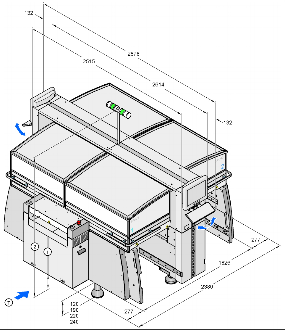
Fig. 4.2 - 1 Dimensions of the HF machine in millimeters - View of the PCB input side
(1) PCB input side
(2) Height of the main fault indicator (max. 2075 mm depending on the PCB transport height)
(T) Direction of PCB transport
User Manual SIPLACE HF Series 4 Setting up and commissioning
Software Version SR.505.xx 05/2004 US Edition 4.2 Dimensions of the placement systems
143
4
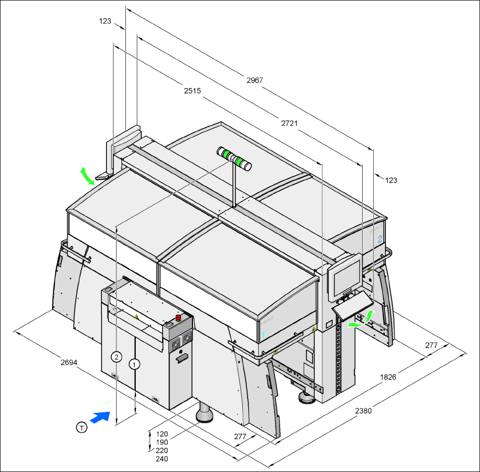
Fig. 4.2 - 2 Dimensions of the HF/3 machine in millimeters - View of the PCB input side
(1) PCB input side
(2) Height of the main fault indicator (max. 2075 mm depending on the PCB transport height)
(T) Direction of PCB transport
4 Setting up and commissioning User Manual SIPLACE HF Series
4.2 Dimensions of the placement systems Software Version SR.505.xx 05/2004 US Edition
144
4
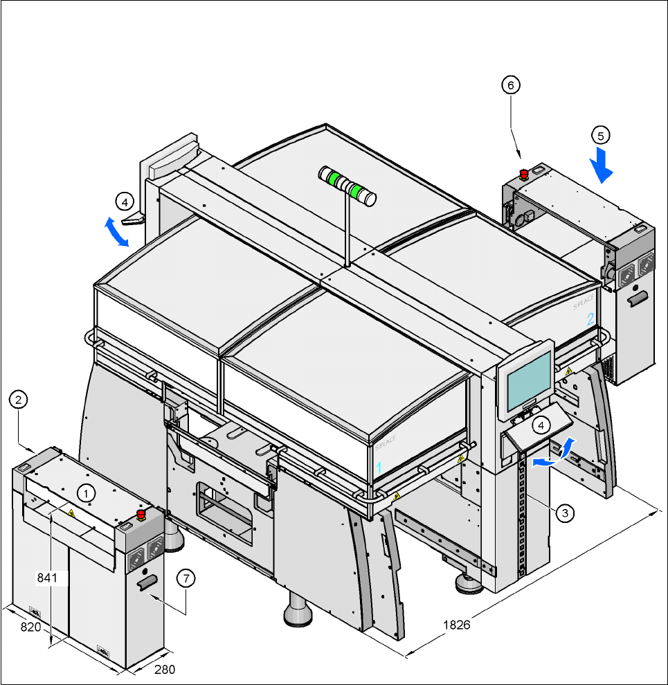
Fig. 4.2 - 3 Dimension of the machine in millimeters - Extension kits removed
(1) Extension kit on the PCB input side - removed for delivery
(2) Computer unit, in extension kit (1)
(3) Pneumatic unit, behind the cover
(4) Fold-down keyboards
(5) Extension kit on the PCB output side - may be removed if necessary
(6) Axis unit, in extension kit (5) - HF: gantries 1 and 3, HF/3: gantry 3
(7) Axis unit, in extension kit (1) - HF/3: gantries 1 and 4