00193922-01.pdf - 第150页
4 Setting up and commissioning User Manual SIPLACE HF Series 4.3 Delivery configuration and transport Sof tware Version S R.505.xx 05/2004 US E dition 150 4.3.3.4 F ork-lif t atta chment point s on the transport crate At…

User Manual SIPLACE HF Series 4 Setting up and commissioning
Software Version SR.505.xx 05/2004 US Edition 4.3 Delivery configuration and transport
149
be important when fine-tuning the machine.
The electrical plug-in connections on the conveyor motor and the conveyor light barrier for the
left-hand track are then easily accessible on the dual conveyor.
– The input conveyors of the single and dual conveyor are dismantled. The electrical cables to
the conveyor motors and light barriers are disconnected.
– Both keyboards (point 4 in Fig. 4.2 - 3
) are folded down vertically.
– The main fault indicator is dismantled (point 6 in Fig. 4.2 - 3
).
– All the gantry axes are fixed with shipping braces.
4.3.3 Transporting the placement machine in the crate
4.3.3.1 Services
As a service, SIEMENS L&A can fully integrate the SIPLACE HF placement machine into your
production line. With our extensive expertise and by using the right tools and equipment, we can
ensure that the installation process runs smoothly and efficiently. However, this will require you to
clarify the infrastructure aspects in advance and make any necessary changes at your production
facility.
Please note that the safest way to transport the placement machine is always in the transport crate
- or at the very least on the pallet. This will prevent serious damage to the machine caused by the
feet colliding with obstacles, for example.
4.3.3.2 Safety instructions
WARNING
– The applicable accident prevention regulations concerning the transportation of heavy goods
must be followed.
– There is a risk that the machine will tip over if you do not use the fork-lift specified in section
4.3.3.3
to transport the placement machine.
– In particular, you should wear safety boots to minimize the risk of crushing your feet.
4.3.3.3 Means of transport
Use a fork-lift truck with the following specification to carry the machine in its crate:
Fork length: min. 1800 mm
Carrying power: min. 6000 kg
Clear width between forks: min. 350 mm 4

4 Setting up and commissioning User Manual SIPLACE HF Series
4.3 Delivery configuration and transport Software Version SR.505.xx 05/2004 US Edition
150
4.3.3.4 Fork-lift attachment points on the transport crate
Attach the fork-lift only at the points identified by (A) in Fig. 4.3 - 1. We recommend that you keep
the crate and packaging for later use.
WARNING
If you still decide to transport the placement machine without a crate or pallet, you MUST follow
the instructions in the next section to avoid serious damage to your machine.
4.3.4 Transporting the placement machine without a crate or pallet
4.3.4.1 Safety instructions
WARNING
Æ The applicable accident prevention regulations concerning the transportation of heavy goods
must be followed.
Æ In particular, you should wear safety boots to minimize the risk of crushing your feet.
Æ Read this section in full before transporting the machine to avoid severe damage.
Æ When you are transporting the machine, make sure that all the feet are clear of the floor. If they
are not clear, the feet will drag along the floor and bump into obstacles. This could damage the
machine foot thread in the machine frame.
4.3.4.2 Means of transport
Use a fork-lift truck with the following specification to carry the machine:
Fork length: min. 1800 mm 4
Carrying power: min. 6000 kg 4
Distance between forks with the forks running parallel to the
direction of PCB transport: 420 mm 4
Distance between forks with the forks running across the
direction of PCB transport: 800 mm - 900 mm 4
User Manual SIPLACE HF Series 4 Setting up and commissioning
Software Version SR.505.xx 05/2004 US Edition 4.3 Delivery configuration and transport
151
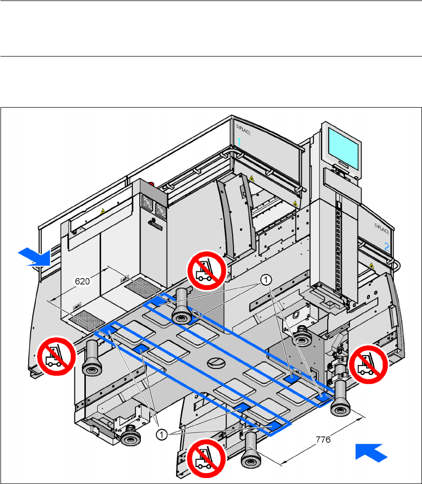
4.3.4.3 Points for attaching the fork-lift on the placement machine
The next two diagrams show the fork-lift attachment points on the placement machine if you want
to lift the machine from the pallet or transport it without a pallet.
NOTE
Always use a pallet and fork-lift to transport the placement machine over longer distances in
order to avoid damaging the machine.
Forks parallel to the PCB conveyor 4
4
Fig. 4.3 - 2 Contact surfaces - Forks parallel to the direction of PCB transport
(1) Contact surfaces for the forks of the fork-lift