00193922-01.pdf - 第156页
4 Setting up and commissioning User Manual SIPLACE HF Series 4.4 Infrastructure at t he installation location Software Version SR. 505.xx 05/2004 US Edition 156 4.4.2 Compressed air supply 4.4.2.1 Chec king the compres s…

User Manual SIPLACE HF Series 4 Setting up and commissioning
Software Version SR.505.xx 05/2004 US Edition 4.4 Infrastructure at the installation location
155
4.4 Infrastructure at the installation location
4.4.1 Recommendations concerning the quality of the foundation
The foundation for the placement machine should be firm and flat since dynamic forces can create
vibrations when the placement machine is used. The size of the vibrations depends on the con-
struction of the foundation. The following are suitable provided that the floor loading parameters,
etc, are not exceeded:
– Reinforced concrete ceiling constructions, e.g. ceilings in production halls
– Reinforced concrete floor slabs, e.g. concrete floors in production halls without a basement
– Rooms with double floors, provided that a stable foundation is included in the space between
them. The same set-up conditions apply to this intermediate foundation, which can be made
from steel girders or concrete.
4.4.1.1 Machine weight and floor loading
4.4.1.2 Vibration limits
The placement machine is not sensitive to ground vibration, but the following vibration limits
should still be observed.
4
Weight of basic machine 3800 kg (HF), 3850 kg (HF/3)
Weight (fully equipped) 4700 kg (HF), 4750 (HF/3)
Footprint 6.01 m² (HF), 6.48 m² (HF/3)
Number of machine feet 6
Load per unit area of the foundation Min. 1561 kg/m² (HF)
Min. 1590 kg/m² (HF/3)
Specific floor loading per foot
6 machine feet
3 machine feet
75.3 N/cm²
150.6 N/cm²
Parameters Values
Third-octave spectral value of the vibration speed
5 - 100 Hz v < 250 µm/s
v
max
value on the time curve v
max
< 1.5 mm/s
4 Setting up and commissioning User Manual SIPLACE HF Series
4.4 Infrastructure at the installation location Software Version SR.505.xx 05/2004 US Edition
156
4.4.2 Compressed air supply
4.4.2.1 Checking the compressed air supply
Check that the compressed air supply conforms to the prescribed machine specifications (see ta-
ble in section 3.3
, page 91).
PLEASE NOTE:
The document entitled "Network configuration (electrical and compressed air) for SMD systems
on the customer's premises", part no. 00191409-xx, describes the action that can be taken to
meet the required specifications.
Æ Record the compressed air characteristics at the installation location.
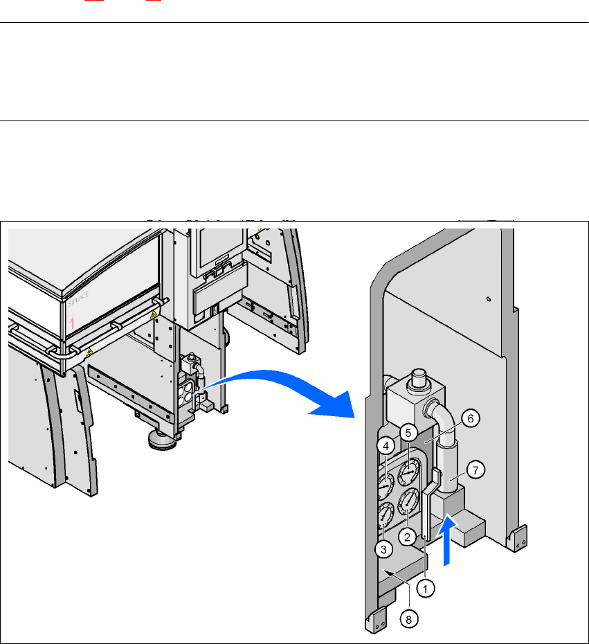
4.4.2.2 Compressed air connection on the placement machine
4
Fig. 4.4 - 1 Compressed air line connection
(1) Stop valve in the "OPEN" position
(2) Manometer for the machine component supply pressure
Desired pressure: 0.48 ± 0.025 MPa, 4.8 ± 0.25 bar (display range 0 - 0.6 MPa, 0 - 6 bar)
(3) Manometer for the gantry distributor supply pressure
User Manual SIPLACE HF Series 4 Setting up and commissioning
Software Version SR.505.xx 05/2004 US Edition 4.4 Infrastructure at the installation location
157
Desired pressure: 0.46 ± 0.01 MPa, 4.6 ± 0.1 bar (display range 0 - 0.6 MPa, 0 - 6 bar)
(4) Manometer for the bulk case feeder supply pressure
Desired pressure: 0.25 MPa ± 0.05 MPa (2.5 bar ± 0.5 bar (display range: 0 - 0.6 MPa, 0 - 6 bar)
(5) Manometer for the input pressure
Desired pressure: 0.5 - 1.0 MPa, 5 - 10 bar (display range: 0 - 1.0 MPa, 0 - 10 bar)
(6) Compressed air filter
(7) Compressed air connection
(8) Hexagon socket head screw for fixing the pneumatic board
WARNING
NEVER detach compressed air lines while they are still pressurized. Risk of injury. 4
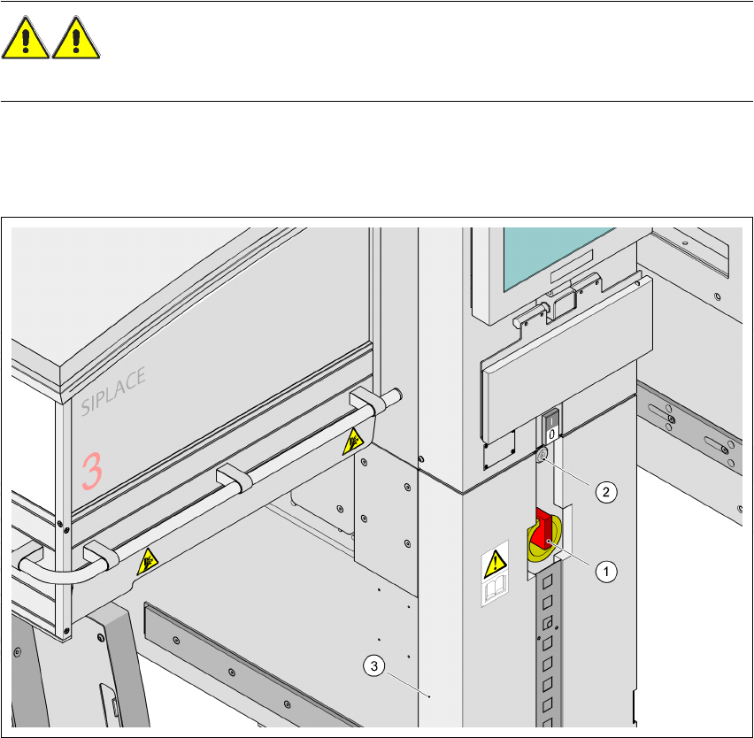
4.4.3 Main power supply
4
Fig. 4.4 - 2 Position of the power supply on the machine
4
(1) Main power switch
(2) Lock
(3) Cover