00193922-01.pdf - 第161页
User Manual SIPLAC E HF Series 4 Setting up and commissioning Software Vers ion SR.505.xx 05/2004 US Edition 4.4 Infrastructure at the inst allation location 161 4.4.3.5 Checking the inrush curr ent limit ation jumpers T…
4 Setting up and commissioning User Manual SIPLACE HF Series
4.4 Infrastructure at the installation location Software Version SR.505.xx 05/2004 US Edition
160
4.4.3.4 Connecting the power supply cable
4
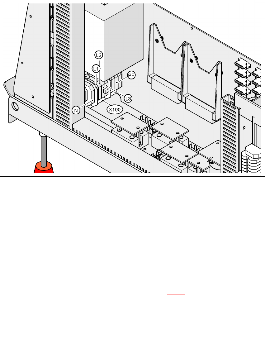
Fig. 4.4 - 4 Terminal panel for connecting the power cable
4
(L1) Three-phase
(L2) Three-phase
(L3) Three-phase
(N) Neutral conductor
(PE) Protective ground wire
(X100) Terminal panel
Æ Crimp a ferrule onto each end of the wire.
Æ Loosen the nuts on the angled cable gland (item 2 in Fig. 4.4 - 3).
Æ Fold up the angled cable gland.
Æ Feed the power supply cable through the angled cable gland to the terminal panel X100 (see
X100 in Fig. 4.4 - 4
).
Æ Connect the cable to the terminal and ensure that it has a sufficient bending radius. The wires
must not be kinked.
Æ Fold up the angled cable gland (item 2 in Fig. 4.4 - 3) and tighten the nuts hand-tight.
User Manual SIPLACE HF Series 4 Setting up and commissioning
Software Version SR.505.xx 05/2004 US Edition 4.4 Infrastructure at the installation location
161
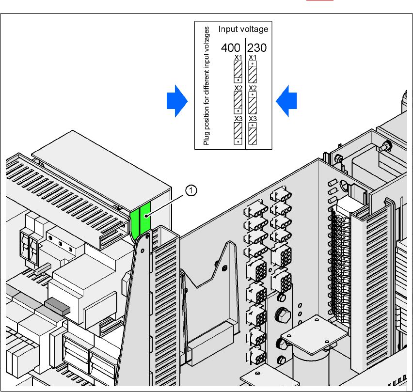
4.4.3.5 Checking the inrush current limitation jumpers
The inrush current limitation must be configured in relation to the supply voltage. This is done us-
ing plug-in jumpers on the inrush current limitation board (item 1 in Fig. 4.4 - 5
).
4
Fig. 4.4 - 5 Position of the board and connectors for the inrush current limitation
4
(1) Inrush current limitation board
X1, X2, X3 Connectors for configuring the inrush current limitation
Æ Check the jumper assignment and correct if necessary.
3 x 380 VAC
3 x 400 VAC
3 x 415 VAC
3 x 208 VAC
3 x 230 VAC
4 Setting up and commissioning User Manual SIPLACE HF Series
4.5 Setting up the placement machine Software Version SR.505.xx 05/2004 US Edition
162
4.5 Setting up the placement machine
4.5.1 PCB transport height on the machine
The machine can be set to the following PCB transport heights:
830 mm ± 15 mm Standard height 4
900 mm ± 15 mm SMEMA height 4
930 mm ± 15 mm SMEMA height 4
950 mm ± 15 mm SMEMA height 4
NOTE
The PCB transport height is the distance between the top edge of the PCB conveyor and the bot-
tom edge of the machine feet.
4.5.2 Warning instructions
DANGER
Only SIEMENS engineers or qualified people are permitted to set up and commission the place-
ment machine.
Æ Always follow the applicable accident prevention regulations.
Æ Never lie beneath the machine in order to attach the machine feet. All the modules and parts
can be fitted from the spaces for the component feeder tables. If you nevertheless have to carry
out assembly work underneath the machine, then you must secure the machine by suitable
means. The fork-lift must not be used as the only support.
Æ Make sure that the gantries are positioned over the PCB conveyor area so that you do not re-
strict your head movement during assembly, thus excluding the risk of injury.
Æ Two people will be needed to adjust the height of the placement machine:
– one person to carry out the necessary assembly work,
– the other person to watch the raised machine during assembly and ensure that it does not
move.
Æ Wear special safety boots to protect your feet. Each machine foot weighs 6.75 kg.