00193922-01.pdf - 第166页
4 Setting up and commissioning User Manual SIPLACE HF Series 4.5 Setting up the placement machine Software Version SR.505.x x 05/2004 US Edition 166 4 Fig. 4.5 - 2 Placement m achine feet 4 (1) Machine foot (2) "HS5…

User Manual SIPLACE HF Series 4 Setting up and commissioning
Software Version SR.505.xx 05/2004 US Edition 4.5 Setting up the placement machine
165
frame, since this would deform the machine frame.
Æ Make sure that the forks are evenly loaded when you lift the machine. A firm support between
the forks and placement machine will prevent the machine tilting when it is raised. This will also
prevent a one-sided load on the machine feet, which would deform the fixing of the machine
feet. We recommend that a second person watch the machine as it is raised, and make sure
that the machine does not tip to one side when lifted with the fork-lift.
Æ With the fork-lift, raise the machine approximately 35 cm. This will avoid any risk of injuring your
feet if you lower the machine feet accidentally.
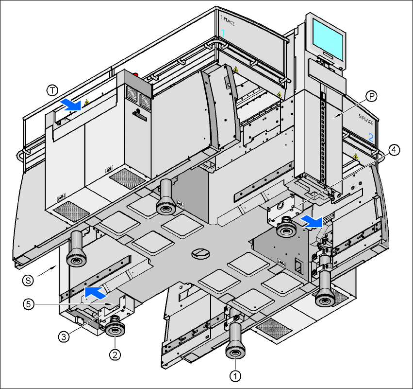
The placement machine stands on 6 feet.
– 4 machine feet (item 1 in Fig. 4.5 - 2
)
– 2 "HS50" machine feet (item 2 in Fig. 4.5 - 2
) with 2 spacers (items 3 and 4 in Fig. 4.5 - 2)
for adjusting the height, if necessary.
4 Setting up and commissioning User Manual SIPLACE HF Series
4.5 Setting up the placement machine Software Version SR.505.xx 05/2004 US Edition
166
4
Fig. 4.5 - 2 Placement machine feet
4
(1) Machine foot
(2) "HS50" machine foot
(3) Spacer on the pneumatic unit side
(4) Spacer on the power supply unit side
(5) Threaded hole for the "HS50" machine foot
(T) Direction of PCB transport
(P) Pneumatic unit
(S) Power supply unit
User Manual SIPLACE HF Series 4 Setting up and commissioning
Software Version SR.505.xx 05/2004 US Edition 4.5 Setting up the placement machine
167
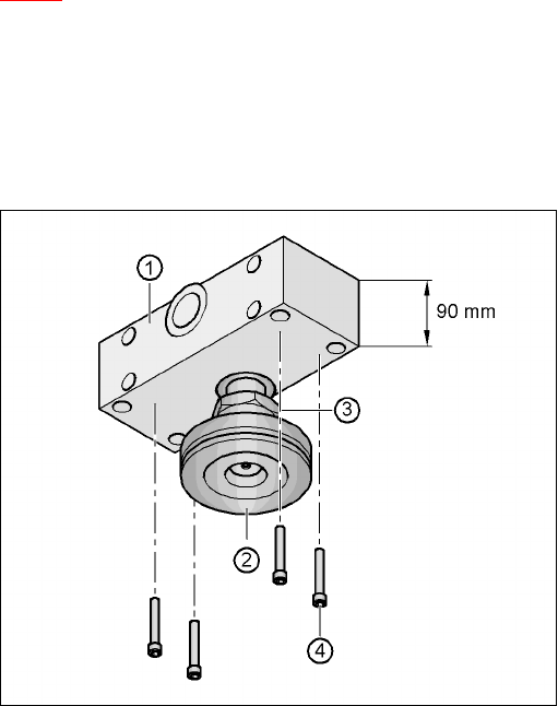
4.5.4.1 Presetting the height of the "HS50" machine feet
The "HS50" machine feet are preset first. The spacer must be bolted to the underside in the cor-
rect position for the machine height.
Setting the PCB transport height to 830 mm 4
You will not need a spacer for a PCB transport height of 830 mm.
Æ Screw the "HS50" machine foot as far as possible into the thread provided (see point 5 in Fig.
4.5 - 2
).
Setting the PCB transport height to 900 mm 4
You will need the spacer for a PCB transport height of 900 mm.
Æ Align the spacer so that the 90 mm side is vertical and the hole for the "HS50" machine foot
points downwards.
4
4
4
4
4
4
4
4
4
4
4
4
Fig. 4.5 - 3 Alignment of the spacer for a transport height of 900 mm
4
(1) Spacer height 90 mm
(2) "HS50" machine foot
(3) M24 lock nut
(4) Hexagon socket head screw M12x80, 4x