00193922-01.pdf - 第175页
User Manual SIPLAC E HF Series 4 Setting up and commissioning Software Version SR.505.xx 05/2004 US Edition 4. 5 Setting up the placement machine 175 Æ Remove bo th covers (item 5 in Fi g. 4.5 - 7 ). CAUTION 4 Do no t un…
4 Setting up and commissioning User Manual SIPLACE HF Series
4.5 Setting up the placement machine Software Version SR.505.xx 05/2004 US Edition
174
4.5.7 Fitting the extension kit on the PCB input side
4.5.7.1 Tools
– Allen keys, DIN 911, set
– Machine key
4.5.7.2 Assembly
4
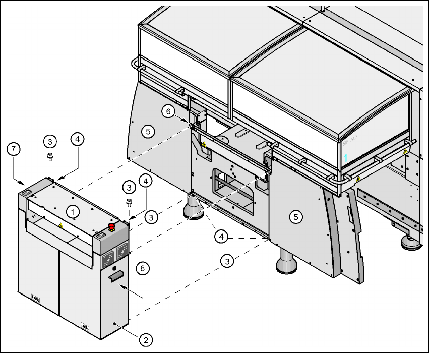
Fig. 4.5 - 7 Fitting the extension kit on the PCB input side
(1) Extension kit
(2) Doors
(3) Fillister head screw DIN 912, M6x16 and washer
(4) Ground connection
(5) Cover
(6) Drawer unit rail
(7) Computer unit
(8) Axis unit (HF/3)
User Manual SIPLACE HF Series 4 Setting up and commissioning
Software Version SR.505.xx 05/2004 US Edition 4.5 Setting up the placement machine
175
Æ Remove both covers (item 5 in Fig. 4.5 - 7).
CAUTION 4
Do not unscrew the three bottom screws straight away. Simply loosen them so that the cover
does not fall off.
Æ Detach the ground cable from the cover.
Æ Remove both doors (item 2 in Fig. 4.5 - 7) from the extension kit (item 1).
PLEASE NOTE: 4
To avoid damage, we recommend that a second person help to assemble the extension kit.
Æ Lift the extension kit (item 1 in Fig. 4.5 - 7) against the machine frame and position it so that
the two assembly brackets lie on the pull-out rail (item 6 in Fig. 4.5 - 7
).
CAUTION 4
Make sure that the extension kit does not collide with the hexagonal shaft of the PCB con-
veyor and thus become bent.
Æ Fix the extension kit with 4 fillister head screws M6x16 and washers.
4.5.7.3 Fixing the hexagonal shaft guide
Æ On the single conveyor, fix
one
guide for the hexagonal shaft (item 8 in Fig.
4.5 - 6
) to the extension kit using two fillister head screws M6x16 and washers.
Æ On the double conveyor, fix two guides for the hexagonal shaft (item 8 in Fig. 4.5 - 6) to the
extension kit using two fillister head screws M6x16 and washers.
4 Setting up and commissioning User Manual SIPLACE HF Series
4.5 Setting up the placement machine Software Version SR.505.xx 05/2004 US Edition
176
4.5.7.4 Connecting the power cables
4
4.5.7.5 Fitting the grounding cable for the doors
Æ Fix the two grounding cables for the doors (item 4 in Fig. 4.5 - 7) to the machine frame as fol-
lows:
4
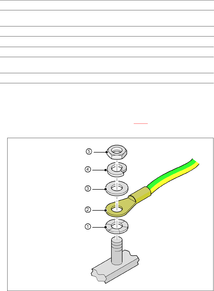
Fig. 4.5 - 8 Fitting the grounding cable
Left side of the extension kit with Connector/cable To connector/cable
Start/Stop button /
Switch on PCB cover flap
X61/03004703 X61/03002537
Protective cover switch, location 4 X54/03006476 X54/03002540
Right side of the extension kit with Connector/cable To connector/cable
Emergency stop button
Start/Stop button
X64/03004704 X64/03002538
Protective cover switch, location 1 X51/03006476 X51/03002539
Hex nut M5
Spring washer M5, DIN 7980
Washer M5, DIN 125
Cable lug, annular
Contact washer