00193922-01.pdf - 第178页
4 Setting up and commissioning User Manual SIPLACE HF Series 4.5 Setting up the placement machine Software Version SR.505.x x 05/2004 US Edition 178 4.5.8 Inst alling the computer unit on HF and HF/3 4.5.8.1 Computer uni…
User Manual SIPLACE HF Series 4 Setting up and commissioning
Software Version SR.505.xx 05/2004 US Edition 4.5 Setting up the placement machine
177
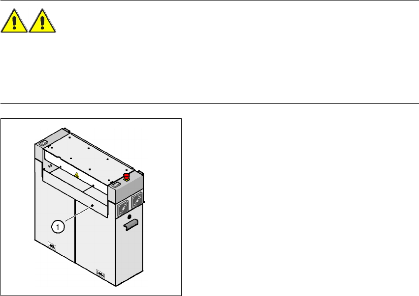
4.5.7.6 Installing the "bottom" hand guard
The machines from the HF series are supplied with just
one
"bottom" hand guard. If the machines
are installed within a line, then no hand guard is required between immediately adjacent output
and input conveyors.
WARNING
Always fit the "bottom" hand guard (part no. 03003432-01) on the input side of the
first
placement
machine and on the output side of the
last
placement machine of a line using 4 hexagon socket
head screws M4x12. This will prevent your personnel reaching into the machine without authori-
zation.
4
Fig. 4.5 - 9 Fitting the "bottom" hand guard on
the PCB input side
(1)"Bottom" hand guard,
part no. 03003432-01
4 Setting up and commissioning User Manual SIPLACE HF Series
4.5 Setting up the placement machine Software Version SR.505.xx 05/2004 US Edition
178
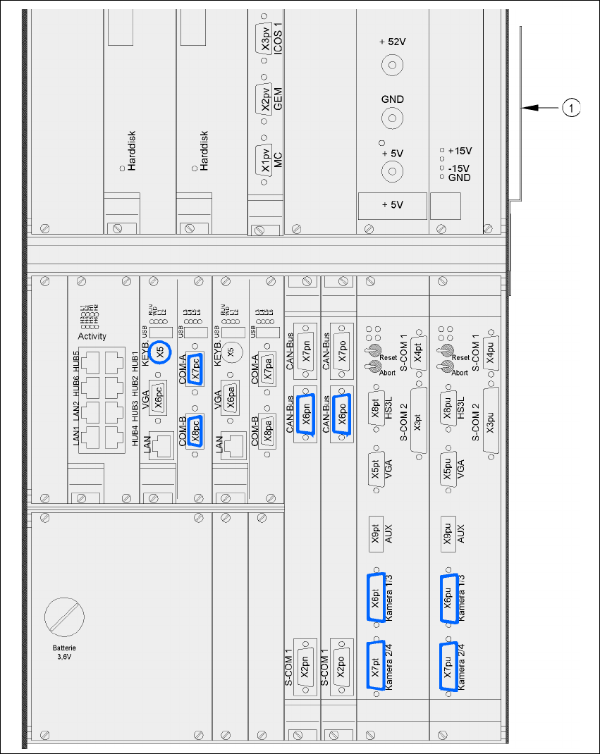
4.5.8 Installing the computer unit on HF and HF/3
4.5.8.1 Computer unit - electrical connection points
4
Fig. 4.5 - 10 Computer unit, front panel - Connecting the plugs
(1) Cable guide plate
User Manual SIPLACE HF Series 4 Setting up and commissioning
Software Version SR.505.xx 05/2004 US Edition 4.5 Setting up the placement machine
179
4
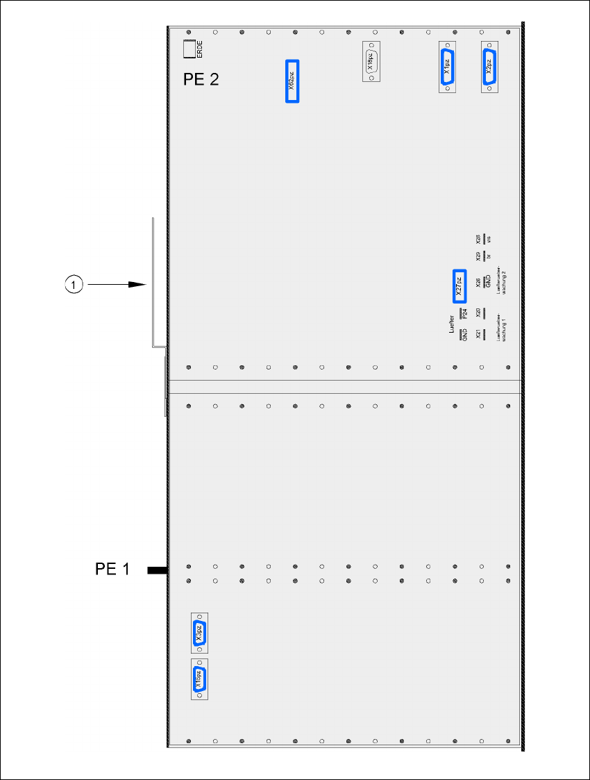
Fig. 4.5 - 11 Computer unit, back panel - Connecting the plugs
(1) Cable guide plate