00193922-01.pdf - 第184页
4 Setting up and commissioning User Manual SIPLACE HF Series 4.5 Setting up the placement machine Software Version SR.505.x x 05/2004 US Edition 184 4.5.9.2 HF/3 axis unit (gantry 1 and gantry 4) - Connecting the plugs Æ…
User Manual SIPLACE HF Series 4 Setting up and commissioning
Software Version SR.505.xx 05/2004 US Edition 4.5 Setting up the placement machine
183
4.5.9 Installing the axis unit on the HF/3 (gantry 1 and gantry 4)
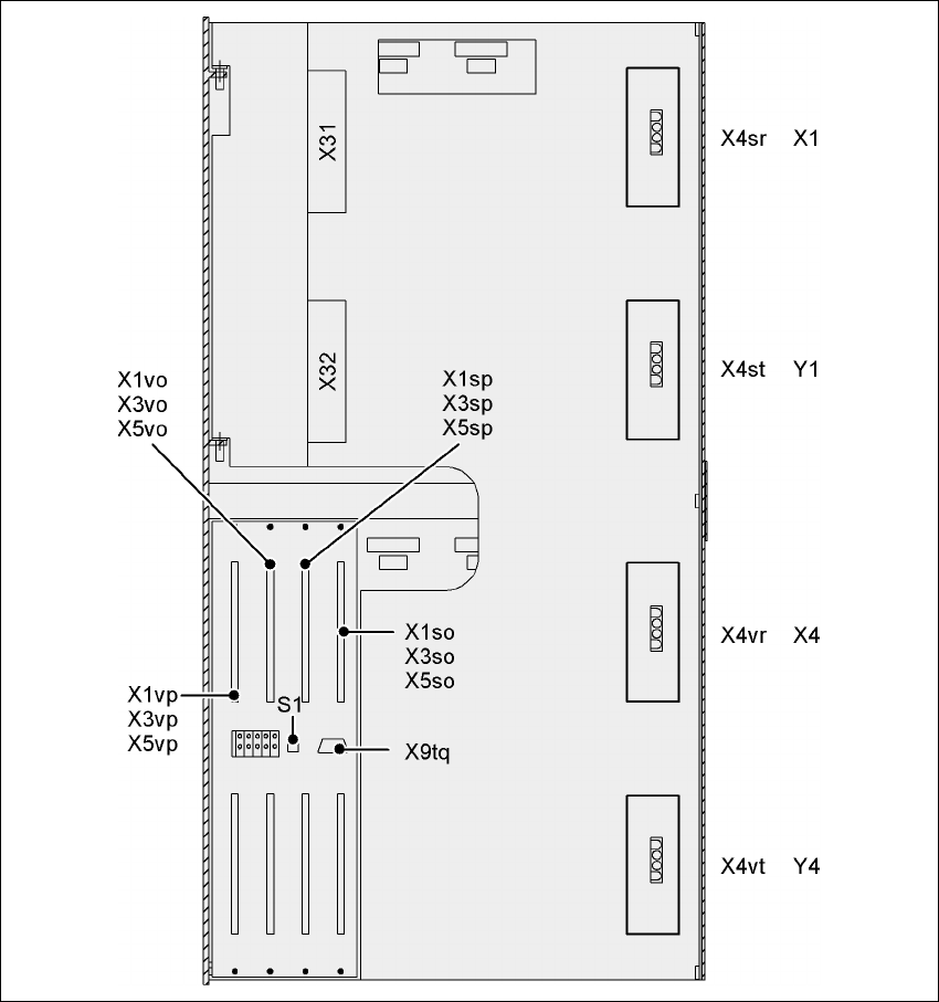
4.5.9.1 HF/3 axis unit (gantry 1 and gantry 4) - electrical connection points
4
Fig. 4.5 - 12 HF/3 axis unit (gantry 1 and gantry 4), rear panel - Connecting the plugs

4 Setting up and commissioning User Manual SIPLACE HF Series
4.5 Setting up the placement machine Software Version SR.505.xx 05/2004 US Edition
184
4.5.9.2 HF/3 axis unit (gantry 1 and gantry 4) - Connecting the plugs
Æ Connect the power cable as shown in the following diagram:
4
4
Æ Check the switch settings for S1
1: OFF
2: OFF
4.5.9.3 Fitting the HF/3 axis unit (gantry 1 and gantry 4)
Æ Carefully lift the axis unit onto the rail in the extension kit.
Æ Make sure that you do not squash any cables.
Axis unit
Gantry 1 and gantry 4
Plug
Connecting cable
NOTE
Plug Cable
X31
X31
03009762
03009763
03009764
03009765
03009766 W1-W5
Secure connector with clips
X32
X32
03009822
03009823
03009824
03009825
03009827
Secure connector with clips
X4sr
X4sr 03009760 Snap connector into place
X4st
X4st 03009761 Snap connector into place
X4vr
X4vr 03009820 Snap connector into place
X4vt
X4vt 03009821 Snap connector into place
X1so
X3so
X5so
X1so
X3so
X5so
03009771
03009772
03009773
Insert as far as the stop
X1sp
X3sp
X5sp
X1sp
X3sp
X5sp
03009774
03009775
03009776
Insert as far as the stop
X1vo
X3vo
X5vo
X1vo
X3vo
X5vo
03009831
03009832
03009833
Insert as far as the stop
X1vp
X3vp
X5vp
X1vp
X3vp
X5vp
03009834
03009835
03009836
Insert as far as the stop
X9tq
X9tq 03010051 Screw tightly

User Manual SIPLACE HF Series 4 Setting up and commissioning
Software Version SR.505.xx 05/2004 US Edition 4.5 Setting up the placement machine
185
Æ Push the axis unit into the extension kit as far as the stop.
Æ Connect the fan cable to the axis unit cable.
Æ Secure the axis unit with the fillister head screw.
Æ Insert the cover.
Æ Fix the grounding cable to the doors (item 2 in Fig. 4.5 - 7, page 174), as shown in Fig. 4.5 - 8
on page 176
.
Æ Lock the doors.
4.5.9.4 Fitting the covers
Æ Fix the grounding cable to each cover (item 5 in Fig. 4.5 - 7, page 174), as shown in Fig. 4.5 -
8 page 176.
Æ Fix each cover to the machine frame with 6 fillister head screws.
NOTE
If you have dismantled the output conveyor, continue from section 4.5.10
"Fitting the output con-
veyor" on page 186. If the output conveyor is still fitted, then continue the assembly work from
section 4.5.14 "Integrating the placement machine into the line" on page 196.