00193922-01.pdf - 第186页
4 Setting up and commissioning User Manual SIPLACE HF Series 4.5 Setting up the placement machine Software Version SR.505.x x 05/2004 US Edition 186 4.5.10 Fitting the output conveyor 4.5.10.1 T ools – Allen keys, DIN 91…

User Manual SIPLACE HF Series 4 Setting up and commissioning
Software Version SR.505.xx 05/2004 US Edition 4.5 Setting up the placement machine
185
Æ Push the axis unit into the extension kit as far as the stop.
Æ Connect the fan cable to the axis unit cable.
Æ Secure the axis unit with the fillister head screw.
Æ Insert the cover.
Æ Fix the grounding cable to the doors (item 2 in Fig. 4.5 - 7, page 174), as shown in Fig. 4.5 - 8
on page 176
.
Æ Lock the doors.
4.5.9.4 Fitting the covers
Æ Fix the grounding cable to each cover (item 5 in Fig. 4.5 - 7, page 174), as shown in Fig. 4.5 -
8 page 176.
Æ Fix each cover to the machine frame with 6 fillister head screws.
NOTE
If you have dismantled the output conveyor, continue from section 4.5.10
"Fitting the output con-
veyor" on page 186. If the output conveyor is still fitted, then continue the assembly work from
section 4.5.14 "Integrating the placement machine into the line" on page 196.
4 Setting up and commissioning User Manual SIPLACE HF Series
4.5 Setting up the placement machine Software Version SR.505.xx 05/2004 US Edition
186
4.5.10 Fitting the output conveyor
4.5.10.1 Tools
– Allen keys, DIN 911, set
– Phillips screwdriver, size 1
4.5.10.2 Assembly
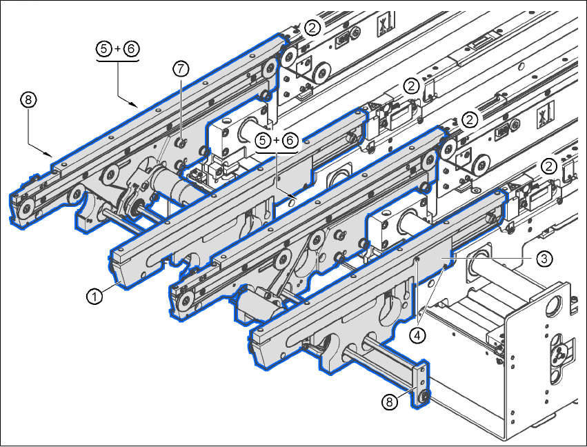
4
Fig. 4.5 - 13 Output conveyor - dual conveyor
4
(1) Output conveyor, panel
(2) Processing conveyor 2, panel
(3) Cable cover 20 x 200
(4) Countersunk screw, ISO 7046, M3x6, 2x per cable cover
(5) Cable cover 20 x 310
(6) Fillister head screw DIN 912, M3x5, 1x per cable cover
(7) Fillister head screw DIN 912, M6x16, and washer, 4x per panel
(8) Guide for hexagonal shaft

User Manual SIPLACE HF Series 4 Setting up and commissioning
Software Version SR.505.xx 05/2004 US Edition 4.5 Setting up the placement machine
187
Æ Remove the cable covers (items 3 and 5 in Fig. 4.5 - 13) from the panels (item 1 in Fig. 4.5 -
13) of the output conveyor.
Æ Carefully place the panel (item 1 in Fig. 4.5 - 13) against the panel on the processing conveyor
(item 2 in Fig. 4.5 - 13
).
CAUTION 4
Be careful not to cut through any of the light barrier or drive motor cables.
Æ Fix each panel using 4 fillister head screws M6x16 and the associated washers (item 7 in Fig.
4.5 - 13
).
Æ Connect the power cable to the light barriers and drive motors.
Æ Fix the cable covers in place (item 3 and 5 in Fig. 4.5 - 13).