00193922-01.pdf - 第188页
4 Setting up and commissioning User Manual SIPLACE HF Series 4.5 Setting up the placement machine Software Version SR.505.x x 05/2004 US Edition 188 4.5.1 1 Fitting the extension kit on the P CB output side 4.5.1 1.1 T o…

User Manual SIPLACE HF Series 4 Setting up and commissioning
Software Version SR.505.xx 05/2004 US Edition 4.5 Setting up the placement machine
187
Æ Remove the cable covers (items 3 and 5 in Fig. 4.5 - 13) from the panels (item 1 in Fig. 4.5 -
13) of the output conveyor.
Æ Carefully place the panel (item 1 in Fig. 4.5 - 13) against the panel on the processing conveyor
(item 2 in Fig. 4.5 - 13
).
CAUTION 4
Be careful not to cut through any of the light barrier or drive motor cables.
Æ Fix each panel using 4 fillister head screws M6x16 and the associated washers (item 7 in Fig.
4.5 - 13
).
Æ Connect the power cable to the light barriers and drive motors.
Æ Fix the cable covers in place (item 3 and 5 in Fig. 4.5 - 13).
4 Setting up and commissioning User Manual SIPLACE HF Series
4.5 Setting up the placement machine Software Version SR.505.xx 05/2004 US Edition
188
4.5.11 Fitting the extension kit on the PCB output side
4.5.11.1 Tools
– Allen keys, DIN 911, set
– Machine key
4.5.11.2 Assembly
4
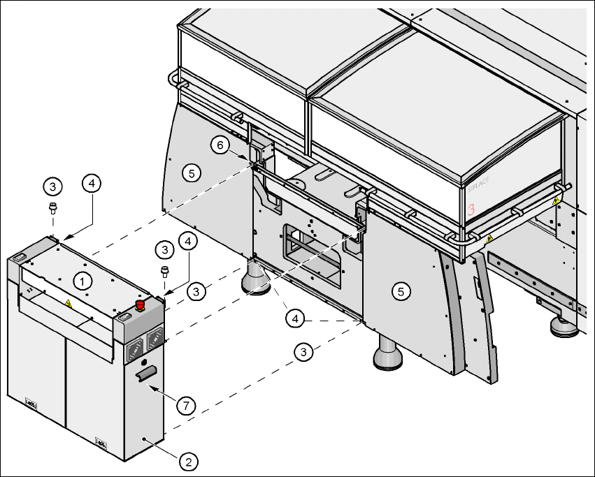
Fig. 4.5 - 14 Fitting the extension kit on the PCB output side
(1) Extension kit
(2) Doors
(3) Fillister head screw DIN 912, M6x16 and washer
(4) Ground connection
(5) Cover
(6) Drawer unit rail
(7) Axis unit (HF) or axis unit, gantry 3 (HF/3)
User Manual SIPLACE HF Series 4 Setting up and commissioning
Software Version SR.505.xx 05/2004 US Edition 4.5 Setting up the placement machine
189
Æ Remove both covers (item 5 in Fig. 4.5 - 14).
CAUTION 4
Do not unscrew the three bottom screws straight away. Simply loosen them so that the cover
does not fall off.
Æ Detach the ground cable from the cover.
Æ Remove both doors (item 2 in Fig. 4.5 - 14) from the extension kit (item 1).
PLEASE NOTE: 4
To avoid damage, we recommend that a second person help to assemble the extension kit.
Æ Lift the extension kit (item 1 in Fig. 4.5 - 14) against the machine frame and position it so that
the two assembly brackets lie on the assembly rail (item 6 in Fig. 4.5 - 14
).
CAUTION 4
Make sure that the extension kit does not collide with the hexagonal shaft of the PCB con-
veyor and thus become bent.
Æ Fix the extension kit with 4 fillister head screws M6x16 and washers.
4.5.11.3 Fixing the hexagonal shaft guide
Æ On the single conveyor, fix
one
guide for the hexagonal shaft (item 8 in Fig.
4.5 - 13
) to the extension kit using two fillister head screws M6x16 and washers.
Æ On the double conveyor, fix two guides for the hexagonal shaft (item 8 in Fig. 4.5 - 13) to the
extension kit using two fillister head screws M6x16 and washers.