00193922-01.pdf - 第190页
4 Setting up and commissioning User Manual SIPLACE HF Series 4.5 Setting up the placement machine Software Version SR.505.x x 05/2004 US Edition 190 4.5.1 1.4 Connecting the power cables 4 4.5.1 1.5 Fitting the g roundin…
User Manual SIPLACE HF Series 4 Setting up and commissioning
Software Version SR.505.xx 05/2004 US Edition 4.5 Setting up the placement machine
189
Æ Remove both covers (item 5 in Fig. 4.5 - 14).
CAUTION 4
Do not unscrew the three bottom screws straight away. Simply loosen them so that the cover
does not fall off.
Æ Detach the ground cable from the cover.
Æ Remove both doors (item 2 in Fig. 4.5 - 14) from the extension kit (item 1).
PLEASE NOTE: 4
To avoid damage, we recommend that a second person help to assemble the extension kit.
Æ Lift the extension kit (item 1 in Fig. 4.5 - 14) against the machine frame and position it so that
the two assembly brackets lie on the assembly rail (item 6 in Fig. 4.5 - 14
).
CAUTION 4
Make sure that the extension kit does not collide with the hexagonal shaft of the PCB con-
veyor and thus become bent.
Æ Fix the extension kit with 4 fillister head screws M6x16 and washers.
4.5.11.3 Fixing the hexagonal shaft guide
Æ On the single conveyor, fix
one
guide for the hexagonal shaft (item 8 in Fig.
4.5 - 13
) to the extension kit using two fillister head screws M6x16 and washers.
Æ On the double conveyor, fix two guides for the hexagonal shaft (item 8 in Fig. 4.5 - 13) to the
extension kit using two fillister head screws M6x16 and washers.
4 Setting up and commissioning User Manual SIPLACE HF Series
4.5 Setting up the placement machine Software Version SR.505.xx 05/2004 US Edition
190
4.5.11.4 Connecting the power cables
4
4.5.11.5 Fitting the grounding cable for the doors
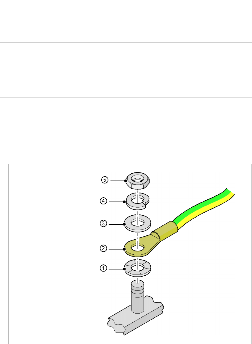
Æ Fix the two grounding cables for the doors (item 4 in Fig. 4.5 - 14) to the machine frame as
follows:
4
Fig. 4.5 - 15 Fitting the grounding cable
Left side of the extension kit with Connector/cable To connector/cable
Emergency stop button
Start/Stop button
X63/03004704 X63/03002526
Protective cover switch, location 2 X52/03006476 X52/03002527
Right side of the extension kit with Connector/cable To connector/cable
Start/Stop button,
switch on PCB cover flap
X62/03004703 X62/03002525
Protective cover switch, location 3 X53/03006476 X53/03002528
Hex nut M5
Spring washer M5, DIN 7980
Washer M5, DIN 125
Cable lug, annular
Contact washer
User Manual SIPLACE HF Series 4 Setting up and commissioning
Software Version SR.505.xx 05/2004 US Edition 4.5 Setting up the placement machine
191
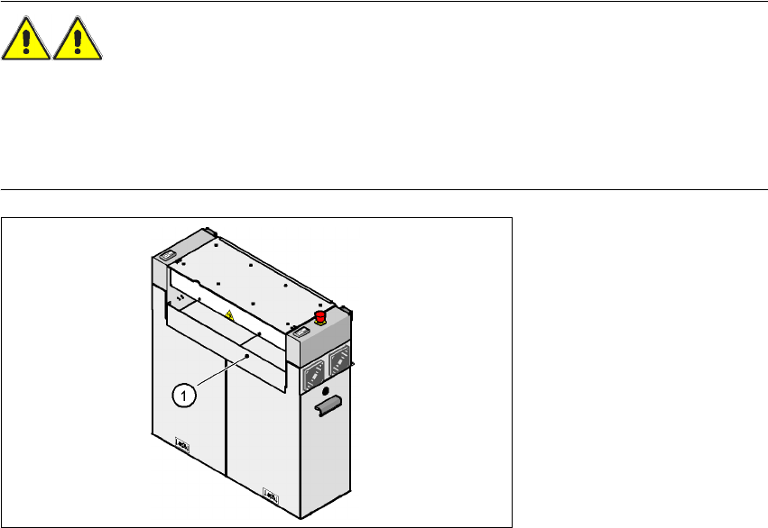
4.5.11.6 Installing the "bottom" hand guard
The machines from the HF series are supplied with just
one
"bottom" hand guard. If the machines
are installed within a line, then no hand guard is required between immediately adjacent output
and input conveyors.
WARNING
Always fit the "bottom" hand guard (part no. 03003432-01) on the input side of the
first
placement
machine and on the output side of the
last
placement machine of a line using 4 hexagon socket
head screws M4x12. This will prevent your personnel reaching into the machine without authori-
zation.
4
Fig. 4.5 - 16 Fitting the "bottom" hand guard on the PCB input side
(1) "Bottom" hand guard, part no. 03003432-01