00193922-01.pdf - 第194页
4 Setting up and commissioning User Manual SIPLACE HF Series 4.5 Setting up the placement machine Software Version SR.505.x x 05/2004 US Edition 194 4.5.12.3 HF/ 3 axis unit (gantry 3) - elect rical connection poi nt s 4…

User Manual SIPLACE HF Series 4 Setting up and commissioning
Software Version SR.505.xx 05/2004 US Edition 4.5 Setting up the placement machine
193
4.5.12.2 HF axis unit - Connecting the plugs
Æ Connect the power cable as shown in the following diagram:
4
4
Æ Check the switch settings for S1
1: OFF
2: ON
Æ Continue from section 4.5.12.5 "Fitting the axis unit", page 195.
HF axis unit
Plug
Connecting cable
NOTE
Plug Cable
X21
X21
03009782
03009783
03009784
03009785
03009786 W1-W5
Secure connector with clips
X22
X22
03009802
03009803
03009804
03009805
03009807
Secure connector with clips
X4tr
X4tr 03009780 Snap connector into place
X4tt
X4tt 03009781 Snap connector into place
X4ur
X4ur 03009800 Snap connector into place
X4ut
X4ut 03009801 Snap connector into place
X1to
X3to
X5to
X1to
X3to
X5to
03009791
03009792
03009793
Insert as far as the stop
X1tp
X3tp
X5tp
X1tp
X3tp
X5tp
03009794
03009795
03009796
Insert as far as the stop
X1uo
X3uo
X5uo
X1uo
X3uo
X5uo
03009811
03009812
03009813
Insert as far as the stop
X1up
X3up
X5up
X1up
X3up
X5up
03009814
03009815
03009816
Insert as far as the stop
X9sq
X9sq 03010056 Screw tightly
4 Setting up and commissioning User Manual SIPLACE HF Series
4.5 Setting up the placement machine Software Version SR.505.xx 05/2004 US Edition
194
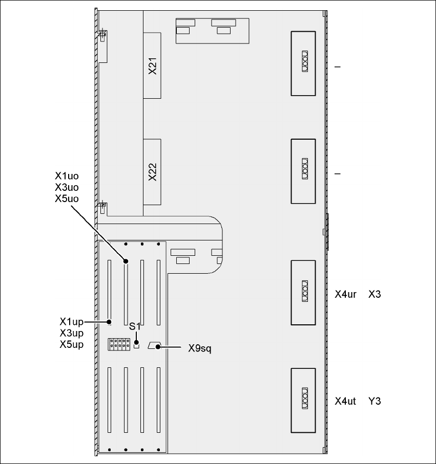
4.5.12.3 HF/3 axis unit (gantry 3) - electrical connection points
4
Fig. 4.5 - 18 HF/3 axis unit (gantry 3), back panel - electrical connection points

User Manual SIPLACE HF Series 4 Setting up and commissioning
Software Version SR.505.xx 05/2004 US Edition 4.5 Setting up the placement machine
195
4.5.12.4 HF/3 axis unit (gantry 3) - Connecting the plugs
Æ Connect the power cable as shown in the following diagram:
4
4
Æ Check the switch settings for S1
1: ON
2: ON
4.5.12.5 Fitting the axis unit
Æ Carefully lift the axis unit onto the rail in the extension kit.
Æ Make sure that you do not squash any cables.
Æ Push the axis unit into the extension kit as far as the stop.
Æ Connect the fan cable to the axis unit cable.
Æ Secure the axis unit with the fillister head screw.
Æ Insert the cover.
Æ Fix the grounding cable to the doors (item 2 in Fig. 4.5 - 14, page 188), as shown in Fig. 4.5 -
15 on page 190.
Æ Lock the doors.
HF/3 axis unit (gantry 3)
plug
Connecting cable
NOTE
Plug Cable
X21
X21
03009782
03009783
03009784
03009785
03009786 W1-W5
Secure connector with clips
X22
X22
03009802
03009803
03009804
03009805
03009807
Secure connector with clips
X4ur
X4ur 03009800 Snap connector into place
X4ut
X4ut 03009801 Snap connector into place
X1uo
X3uo
X5uo
X1uo
X3uo
X5uo
03009811
03009812
03009813
Insert as far as the stop
X1up
X3up
X5up
X1up
X3up
X5up
03009814
03009815
03009816
Insert as far as the stop
X9sq
X9sq 03010056 Screw tightly