00193922-01.pdf - 第204页
4 Setting up and commissioning User Manual SIPLACE HF Series 4.6 Adapting the com ponent trolley to the PCB transport height Software Version S R.505.xx 05/2004 US Edition 204 4.6 Adapti ng the com ponent trolley to the …
User Manual SIPLACE HF Series 4 Setting up and commissioning
Software Version SR.505.xx 05/2004 US Edition 4.5 Setting up the placement machine
203
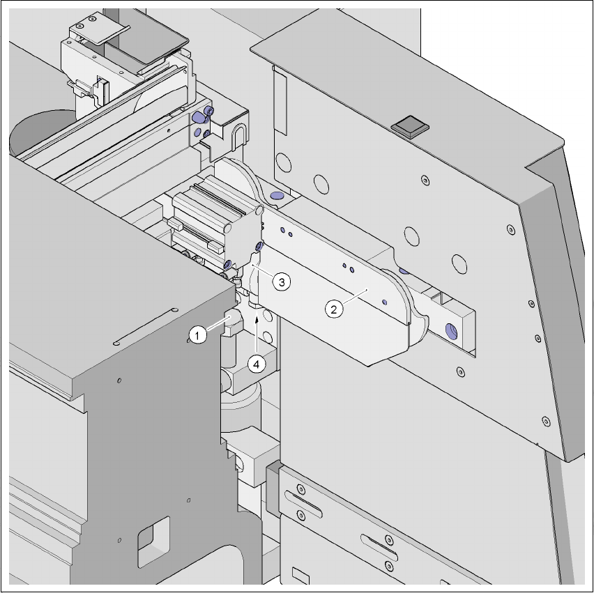
4.5.15.1 Removing the air connection on the component trolley docking unit
4
Fig. 4.5 - 24 Air connection on the cylinder of the component trolley docking unit
4
(1) M24 x 80 hexagon head screw
(2) Component trolley docking unit
(3) Cylinder
(4) Air connection, hexagon nut M10
Æ Use the size 17 open-ended spanner to remove the air connection on the docking unit.
4 Setting up and commissioning User Manual SIPLACE HF Series
4.6 Adapting the component trolley to the PCB transport height Software Version SR.505.xx 05/2004 US Edition
204
4.6 Adapting the component trolley to the PCB trans-
port height
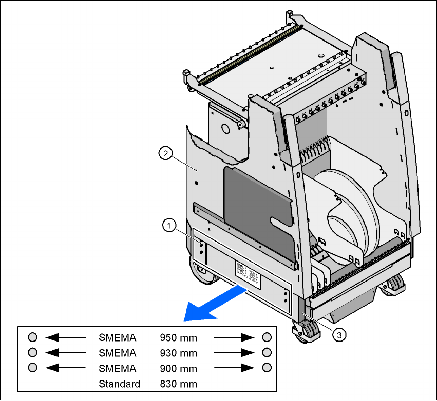
The component trolley can be set to the following PCB transport heights with just a few simple
actions:
830 mm ± 15 mm Standard height
900 mm ± 15 mm SMEMA height
930 mm ± 15 mm SMEMA height
950 mm ± 15 mm SMEMA height 4
4
Fig. 4.6 - 1 Component trolley with a PCB transport height of 950 mm
(1) Pins for marking the height
(2) Component trolley, top part
(3) Component trolley, chassis

User Manual SIPLACE HF Series 4 Setting up and commissioning
Software Version SR.505.xx 05/2004 US Edition 4.6 Adapting the component trolley to the PCB transport height
205
With the default PCB height of 830 mm, all the height marking pins disappear beneath the side
walls of the top part of the component trolley. The marking pins are pushed out by a pressure
spring when the top part is raised. The top part of the component trolley then lies on these marking
pins.
4.6.1 Warning instructions
WARNING
Only Siemens engineers or qualified personnel are permitted to adjust the component trolley
height.
Æ Always follow the applicable accident prevention regulations.
Æ Remove all the feeders from the component table bed if you want to adjust the height of the
component feeder table.
4.6.2 Tools and equipment
You will need the following tools and equipment to adjust the height of the component trolley:
– Flange screwdriver for M6 bolts
– Eye-bolt with M12 thread for raising the top part of the component trolley
– Lifting device for raising the top part of the component trolley, carrying capacity at least 120 kg