00193922-01.pdf - 第207页
User Manual SIPLAC E HF Series 4 Setting up and commissioning Software Version SR.505.xx 05/2004 US Edition 4.6 Adapting the component trolley to the PCB transport height 207 4.6.3.2 Reducing the component troll ey heigh…
4 Setting up and commissioning User Manual SIPLACE HF Series
4.6 Adapting the component trolley to the PCB transport height Software Version SR.505.xx 05/2004 US Edition
206
4.6.3 Changing the component trolley height
WARNING
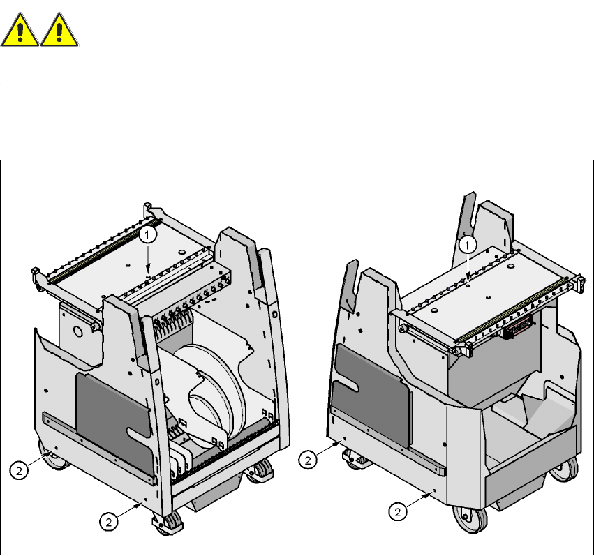
Lift all the feeders off the component trolley bed.
Æ Attach the hooks of the lifting device to the eye-bolt (item 1).
Æ Loosen the 4 flange bolts (item 2)
4
Fig. 4.6 - 2 Positions of the eye-bolt and flange bolts
(1) M12 hole for eye-bolt
(2) Flange bolts M6 x 12, 4x
4.6.3.1 Increasing the component trolley height
Æ Raise the component trolley top part until the pins for the desired height are pushed out.
Æ Slacken the rope of the lifting device slightly until the top part lies on the pin.
Æ Tighten the 4 flange bolts.
Æ Screw the eye-bolt into the component table surface.

User Manual SIPLACE HF Series 4 Setting up and commissioning
Software Version SR.505.xx 05/2004 US Edition 4.6 Adapting the component trolley to the PCB transport height
207
4.6.3.2 Reducing the component trolley height
For this task you will need two other people to press in the height marking pins to allow the top
part to be lowered.
WARNING
Do not use your fingers to press the marking pin back into the openings. Use a flat object, such
as a screwdriver blade or a ruler, otherwise you may hurt your fingertips.
Æ Lower the top part to the required height.
Æ Check that the top part is lying on the marking pins.
Æ Tighten the four flange bolts.
Æ Unscrew the eye-bolt from the component trolley bed.
4 Setting up and commissioning User Manual SIPLACE HF Series
4.6 Adapting the component trolley to the PCB transport height Software Version SR.505.xx 05/2004 US Edition
208