00193922-01.pdf - 第249页
User Manual SIPLAC E HF Series 6 Component han dling Software Version SR.505.xx 05/2004 US Edition 6.2 Technical data for the feeders 249 6.2.14.2 T echnical dat a 6 6 6.2.14.3 Parameters for the surf t ape feeders The p…
6 Component handling User Manual SIPLACE HF Series
6.2 Technical data for the feeders Software Version SR.505.xx 05/2004 US Edition
248
6.2.14 Surftape feeder
6.2.14.1 Overview
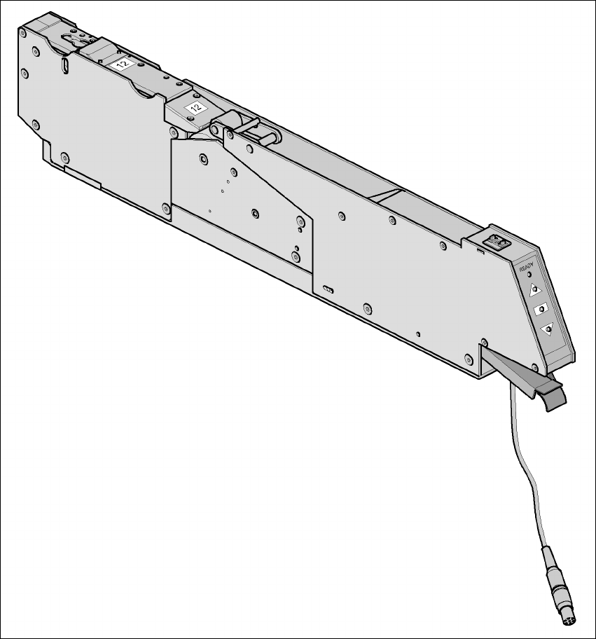
You will need the surftape feeder to supply components for placing bare dies. This feeder has
versions for 8 mm tapes and 12 or 16 mm tapes. 6
6
Fig. 6.2 - 14 Surftape feeder
The surftape feeder can be ordered from Hover-Davis (www.hoverdavis.com). Handling of the
feeder is described in the operating instructions for feeder modules. 6

User Manual SIPLACE HF Series 6 Component handling
Software Version SR.505.xx 05/2004 US Edition 6.2 Technical data for the feeders
249
6.2.14.2 Technical data
6
6
6.2.14.3 Parameters for the surftape feeders
The parameters for the surftape feeders can be modified on the SIPLACE Pro computer.
Tape widths 8/12/16 mm
Recommended tape and component
sizes
8 mm: 1 x 1 mm² - 2.3 x 2.3 mm² components
12 mm: 2.3 x 2.3 mm² - 5 x 5 mm² components
16 mm: 3.8 x 3.8 mm² - 9.5 x 9.5 mm² components
Packaging accuracy of the bare die on
the surf tape
Bare die sizes up to 2.3 x 2.3 mm²: +/- 100 µm, 6 σ
Bare die sizes over 2.3 x 2.3 mm²: +/- 200 µm, 6 σ
(in relation to the center of the pocket)
Required distance between the edges of
the bare dies to the tape pocket
Min. 0.4 mm
Pusher needle Single or triple needle depending on the die size
Tape material Metric
Tape standard IEC 286-3, DIN-IEC-286, EIA 481, and JIS C 0806
Tape reel diameter 7" to 15"
Feeder footprint 1 location on the component table
6 Component handling User Manual SIPLACE HF Series
6.2 Technical data for the feeders Software Version SR.505.xx 05/2004 US Edition
250
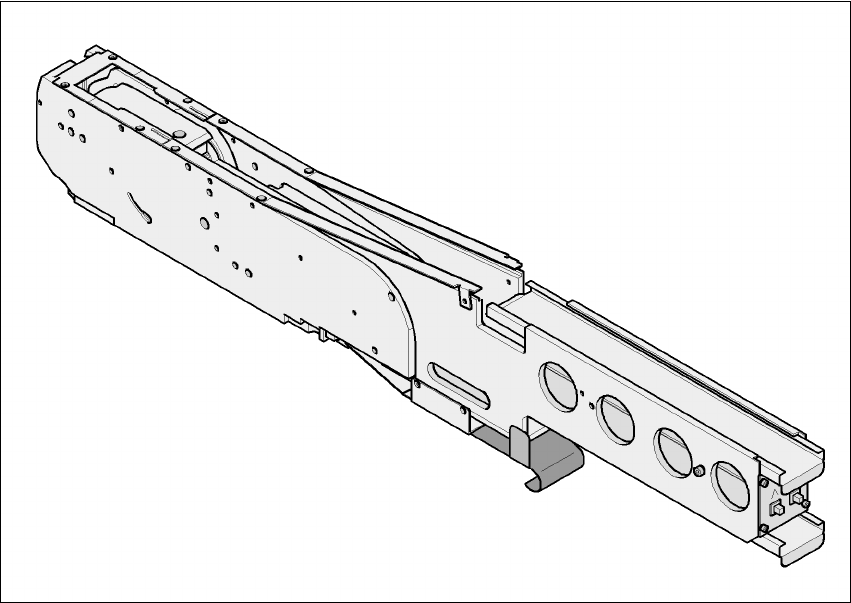
6.2.15 Component disposal module
6
Fig. 6.2 - 15 Component disposal module
6
Part no. 00141200-xx
Width 54.3mm
Tracks per module 1
No. of locations 2
Component range up to 27x27mm² for a pocket size of 30 x 30 mm²
up to 13 x 13 mm² for a pocket size of 15 x 30 mm²
Maximum component height 14 mm
Transport distance (variable) 20 mm for a pocket size of 15 x 30 mm²
36 mm for a pocket size of 30 x 30 mm²