00193922-01.pdf - 第251页
User Manual SIPLAC E HF Series 6 Component han dling Software Version SR.505.xx 05/2004 US Edition 6.2 Technical data for the feeders 251 6.2.15.1 Descriptio n of the f unctions The com ponent dis posal m odule has essen…
6 Component handling User Manual SIPLACE HF Series
6.2 Technical data for the feeders Software Version SR.505.xx 05/2004 US Edition
250
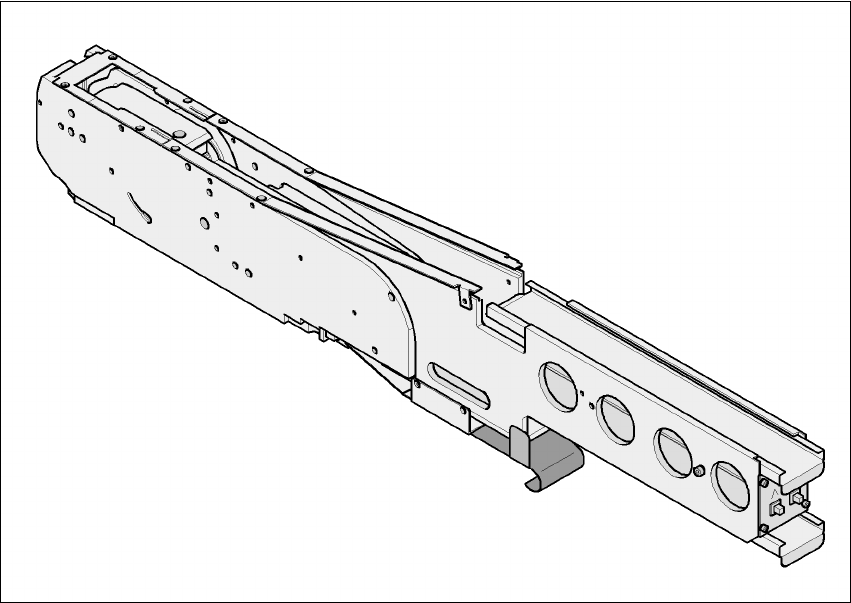
6.2.15 Component disposal module
6
Fig. 6.2 - 15 Component disposal module
6
Part no. 00141200-xx
Width 54.3mm
Tracks per module 1
No. of locations 2
Component range up to 27x27mm² for a pocket size of 30 x 30 mm²
up to 13 x 13 mm² for a pocket size of 15 x 30 mm²
Maximum component height 14 mm
Transport distance (variable) 20 mm for a pocket size of 15 x 30 mm²
36 mm for a pocket size of 30 x 30 mm²

User Manual SIPLACE HF Series 6 Component handling
Software Version SR.505.xx 05/2004 US Edition 6.2 Technical data for the feeders
251
6.2.15.1 Description of the functions
The component disposal module has essentially the same structure as a feeder. The only differ-
ence is that it has an empty tape, rather than a component tape. Faulty components can be placed
in the pockets of this empty tape without damaging them. This means that these components can
subsequently be manually checked, repaired and thus reused. The advantage of the disposal con-
veyor is that the operator can remove the separated components without having to interrupt the
placement process. Once all the pockets on the conveyor belt are full, a message appears on the
monitor, prompting the operator to remove the components. 6
6.2.15.2 System requirements
The following system requirements must be fulfilled in order to use the component disposal mod-
ule: 6
SIPLACE Pro computer software version V 2.0 or later
Station computer software version V 505.xx or later
PLEASE NOTE:
The component disposal module must be configured on the SIPLACE Pro computer and activated
on the station computer. 6
6.2.15.3 Conditions for disposal of components using the component disposal module
A component is placed on the disposal module, if the following conditions are fulfilled: 6
– The component type to be disposed of must be included in the set-up on the SIPLACE Pro
computer.
– The component must be identified for return.
– To segregate identified components that were picked up from a tray, place them back in the
tray. Only components that were wetted with flux in the dip module are placed in the component
disposal module in order to segregate them.
6 Component handling User Manual SIPLACE HF Series
6.2 Technical data for the feeders Software Version SR.505.xx 05/2004 US Edition
252
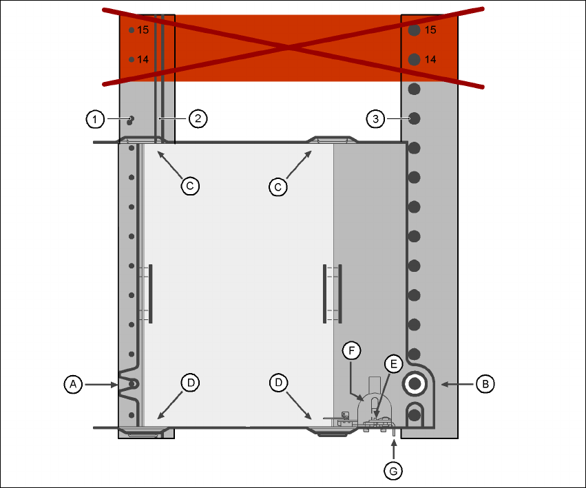
6.2.16 Support for waffle-pack trays (manual tray)
The support for waffle-pack trays allows components to be picked up from individual waffle-pack
trays. The waffle-pack trays are changed manually. 6
6
Fig. 6.2 - 16 Installation
(1) Centering pins
(2) Magnetic rail
(3) Centering ball
(14), (15) This position must not be filled.
The support for waffle-pack trays is placed on the component feeder table, just like a conveyor.
There are two different versions of the support, the only difference being the width. 6
Support for large waffle tray (260x360mm², fills 9 locations)
part no. 00116430-01 and 6
Support for small waffle tray (136x360mm², fills 5 locations)
part no. 00116432-01 6