00193922-01.pdf - 第267页
User Manual SIPLAC E HF Series 6 Component han dling Software Vers ion SR.505.xx 05/2004 US Edition 6.3 Component trolley 267 6.3.8 Feeder fixing The feed er fixing i s an addi tional me chani cal safe ty featur e that p…
6 Component handling User Manual SIPLACE HF Series
6.3 Component trolley Software Version SR.505.xx 05/2004 US Edition
266
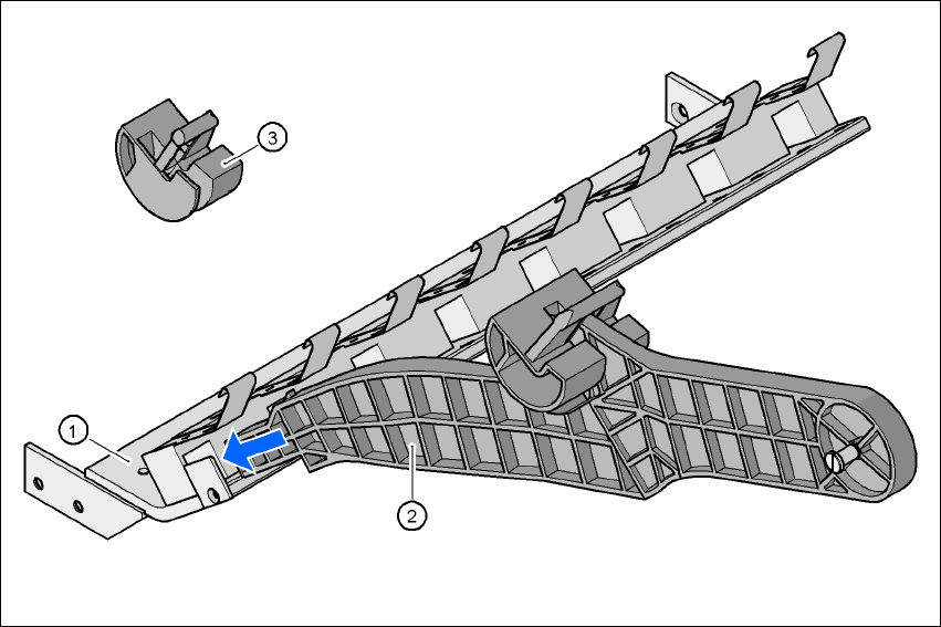
6.3.7 Support for the middle tape reel for 3x8 mm feeders
Type 3x8 mm S feeders transport components to the pick-up position on three tracks. The tape
reels for the two outer tracks are located between the dividing plates in the tape container. The
middle tape reel is arranged over the tape reels for the two outer tracks.
For the middle tape reels you will therefore also need:
– 1 adapter plate for holding the tape reel holder (item 1),
– 1 tape reel holder (item 2) for every two feeders, and
– 1 shortened idler pulley (item 3) for the tape reel holder at location 1 of the component feeder
table.
The adapter plate is fixed inside the component trolley with four fillister head screws, and the tape
reel holders are inserted into the square openings in the adapter plate.
6
Fig. 6.3 - 8 Support for the middle tape reel for 3x8 mm feeders
(1) Adapter plate
(2) Tape reel holder
(3) Idler pulley, shortened
User Manual SIPLACE HF Series 6 Component handling
Software Version SR.505.xx 05/2004 US Edition 6.3 Component trolley
267
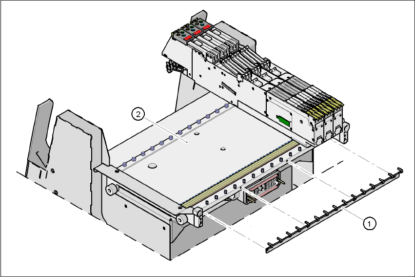
6.3.8 Feeder fixing
The feeder fixing is an additional mechanical safety feature that prevents the conveyor acciden-
tally slipping on the component feeder table and excludes the risk of collision with the placement
head.
The conveyor fixing is fixed to the front of the component feeder table using screws. The claws fix
the feeder feet. One feeder fixing is required for every component trolley.
6
Fig. 6.3 - 9 Feeder fixing
(1) Feeder fixing
(2) Component feeder table
6 Component handling User Manual SIPLACE HF Series
6.4 Matrix tray changer Software Version SR.505.xx 05/2004 US Edition
268
6.4 Matrix tray changer
The use of flatpack ICs is becoming an increasingly significant aspect in the production of flat
modules. These components are now almost exclusively provided in waffle trays. The space re-
quired by waffle trays is relatively large in comparison to the component density, however. The low
component capacity also requires the waffle trays to be changed frequently, which means that the
placement sequence has to be interrupted if the trays are changed manually.
The use of a matrix tray changer eliminates this unnecessary time loss since the waffle trays are
stored and automatically changed. Programmable, random access to up to 100 x waffle-pack
trays also considerably increases the range of components that can be made available.
6.4.1 Description
The matrix tray changer can be used to store and change up to 100 waffle trays fully automatically.
The levels (storage locations in the towers) for the waffle trays are numbered consecutively in as-
cending order from bottom to top.
The towers move independently of one another in the vertical direction until the selected maga-
zine is within range of the feed axis. The horizontal feed axis transports the waffle-pack tray from
the tower into the access area of the placement head.
Tower 1 has 30 levels, each of which can hold 2 JEDEC trays or one large tray up to 240 x 340
mm² from the waffle-pack tray carriers.
Tower 2 has a capacity of 40 levels for JEDEC trays.
A matrix tray changer may be docked in place of a component trolley at locations 2 and 4 on the
HF machine (only at location 2 on HF/3 machines). The draw-in device installed for the component
trolley may be replaced with the docking device for the matrix tray changer. Or conversely, the ma-
trix tray changer can be replaced with a component trolley.
The matrix tray changer has an integral chassis, and is therefore easy to move to other locations.
It is supplied with the PCB transport height implemented for the HF machines, but can easily be
adapted for PCB transport heights of 830, 900, 930 and 950 mm.