00193922-01.pdf - 第278页
7 Station extensions User Manual SIPLACE HF Series 7.1 Nozzle changer Software V ersion SR.505.xx 05/2004 US Edition 278 Fig. 7.1 - 5 Magazine and nozzle garag es (1) Posit ioning fi duci al (2) Locking pl ate (3) Nozzl …

User Manual SIPLACE HF Series 7 Station extensions
Software Version SR.505.xx 05/2004 US Edition 7.1 Nozzle changer
277
7.1.1.5 Description of the functions
The nozzles are seated in nozzle holders and are held in place by a movable locking plate. A
pneumatic cylinder moves the locking plate 6 mm. All the nozzles are either clamped or released,
depending on the position of the locking plate. The default position of the locking plate, i.e. if there
is no nozzle change in progress, is "closed".
Every magazine of the nozzle changer has a positioning fiducial for position detection. The mag-
azine locations are numbered consecutively from 1 - 5 for the "row 1" nozzle changers and from
6 - 10 for the "row 2" (see Fig. 7.1 - 2
and 7.1 - 3). The 12 nozzle holders in the magazines are
also numbered consecutively (see Fig. 7.1 - 5
).
PLEASE NOTE 7
Special magazines are available upon request (contact SIEMENS L&A for details) and will be
numbered differently.
Picking up a nozzle 7
– The Collect&Place head Z axis moves down.
– The locking plate (item 2 in Fig. 7.1 - 5
) opens and releases the nozzles.
– The nozzle is picked up by the sleeve of the Collect&Place head.
– The Z axis moves up.
Setting down a nozzle 7
– The locking plate (item 5 in Fig. 7.1 - 5) opens and releases the nozzle holders.
– The Collect&Place head Z axis moves down and sets the nozzle down.
– The locking plate closes.
– The Collect&Place head Z axis moves up.
Discarding defective nozzles 7
– The Collect&Place head Z axis moves down 14 mm towards the discarding device (item 4 in
Fig. 7.1 - 3
and 7.1 - 2) and thus moves the defective nozzle into the hole in the discarding de-
vice.
– The Z axis moves up again and the nozzle is stripped from the sleeve by spring wires.
– The nozzle drops into the reject bin.
7 Station extensions User Manual SIPLACE HF Series
7.1 Nozzle changer Software Version SR.505.xx 05/2004 US Edition
278
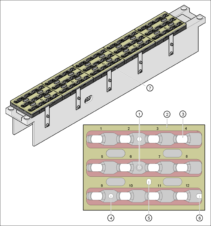
Fig. 7.1 - 5 Magazine and nozzle garages
(1) Positioning fiducial
(2) Locking plate
(3) Nozzle garage
(4) Hole for the parallel pin for centering the magazines
(5) Hole for the parallel pin of the slide mechanism
(6) Slot for the parallel pin for centering the magazines
(7) Magazine

User Manual SIPLACE HF Series 7 Station extensions
Software Version SR.505.xx 05/2004 US Edition 7.1 Nozzle changer
279
7.1.1.6 Notes on operation
Æ When you fill a magazine with a certain nozzle type for the first time, attach an adhesive label
to identify the type.
PLEASE NOTE 7
Fill the magazines off the machine and always replace complete magazines. 7
Æ Open the locking plate and place the nozzles in the nozzle holders.
Æ Close the locking plate so that the nozzles cannot drop out of the magazines.
CAUTION 7
Before you fill magazine, make sure that all the nozzles on the Collect&Place head have
been returned to their magazines. 7
Æ Programming the nozzle changer is described in the SIPLACE Pro user manual.
PLEASE NOTE 7
Æ Do not allow components to drop onto the magazines. If they do, they could jam the locking
plate.
Æ Do not allow components to drop onto free feeder locations. They will stick to the magnetic bar.
Production may have to be interrupted if the feeders are not placed on the component table
correctly. You should therefore regularly clean the magazines and free locations.