00193922-01.pdf - 第303页
User Manual SIPLAC E HF Series 7 Station extensions Software Vers ion SR.505.xx 05/2004 US Edition 7.3 C omponent barcode reader 303 strip. Th e barcod e strips are numbered consecuti vely in intervals of two (1, 3, 5, 7…
7 Station extensions User Manual SIPLACE HF Series
7.3 Component barcode reader Software Version SR.505.xx 05/2004 US Edition
302
7.3 Component barcode reader
7.3.1 General
With the placement system, a barcode reader can be used to check that the track allocation is
correct and to read component data from component reels. A barcode reader can be installed on
both of the operator panels on the placement system. A retrofit kit contains two component bar-
code readers.
7
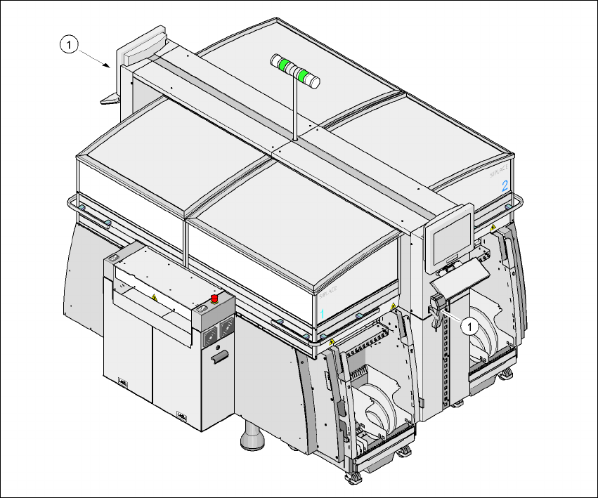
Fig. 7.3 - 1 Component barcode reader
(1) Barcode reader
Track allocation 7
Four-digit barcode strips are attached to the lateral safety screens for the purposes of track allo-
cation. The first digit is used to identify the component table (1, 2, 3, or 4), while the remaining
three digits specify the track number. There are also return barcodes at both ends of the barcode

User Manual SIPLACE HF Series 7 Station extensions
Software Version SR.505.xx 05/2004 US Edition 7.3 Component barcode reader
303
strip. The barcode strips are numbered consecutively in intervals of two (1, 3, 5, 7...) and each
represents 2 tracks (barcode 1 = track 1 and 2).
Components 7
Data can be read from the component reels to compare the stock of components against the quan-
tity specified in the set-up file (refill check), for example.
An audible signal is given when each dataset has been read successfully.
PLEASE NOTE 7
The component barcode reader option must be configured on the SIPLACE Pro computer.
Barcodes that start with the number 1, 2, 3, or 4 and are 4 digits long are interpreted as track bar-
codes. All other barcodes that do not start with number 1, 2, 3, or 4 are regarded as component
barcodes.
7.3.2 Technical data
7
Component barcode reader
Max. resolution 0.13 mm
Scanning speed 36 scans/sec.
Laser class Laser class 1
Degree of protection IP 64
Dimensions 225 x 69 x 67 mm³
Weight 380 g
Cable length 2 m
Influence of ambient light Immune to the direct incidence of normal light and the
indirect incidence of sunlight
Operating temperature - 10°C to + 40°C
Atmospheric humidity Max. 90% (non-condensing)
Compatible barcode types Code 39 (normal / FULL ASCII)
EAN/UPC (family with/without ADD ON
CODABAR
INTERLEAVED 2/5
NORMAL 2/5 (5 bars)
(others available upon request)
7 Station extensions User Manual SIPLACE HF Series
7.4 Dual conveyor Software Version SR.505.xx 05/2004 US Edition
304
7.4 Dual conveyor
7.4.1 Structure of the dual conveyor
The conveyor belts are driven by DC motors. There is a lifting table for clamping the PCBs in each
processing area. The PCB conveyor width can either be set from the user interface or preset in
the placement program.
7
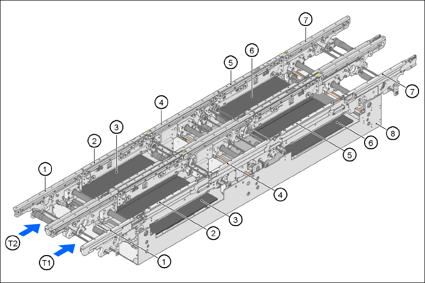
Fig. 7.4 - 1 Structure of the PCB dual conveyor
(1) Input conveyor
(2) Processing conveyor 1
(3) Lifting table 1
(4) Intermediate conveyor
(5) Processing conveyor 2
(6) Lifting table 2
(7) Output conveyor
(8) Assembly trough
T1 Conveyor track 1
T2 Conveyor track 2