00193922-01.pdf - 第308页
7 Station extensions User Manual SIPLACE HF Series 7.5 PCB barcode reader Software V ersion SR.505.xx 05/2004 US Edition 308 7.5 PCB barcode reade r 7.5.1 Ove rview The PCB barcode reader is used to a utomatica lly rec o…

User Manual SIPLACE HF Series 7 Station extensions
Software Version SR.505.xx 05/2004 US Edition 7.4 Dual conveyor
307
7.4.9 Technical data – dual conveyor
7
7
7
Fixed conveyor side Right or left
PCB format
Standard (length x width)
Option "Long board"
Dual conveyor in "single conveyor" mode
Standard
Option "Long board"
50 x 50 mm² to 450 x 250 mm²
50 x 80 mm² to 610 x 250 mm²
50 x 50 mm² to 450 x 450 mm²
50 x 80 mm² to 610 x 450 mm²
PCB thickness
Standard 0.3 mm to 4.5 mm ± 0.2 mm
(thicker PCBs available upon request)
Max. PCB warpage Up: 6 mm - PCB thickness
Down: 0.3 mm + PCB thickness
PCB weight Max. 3 kg
Clearance on PCB underside
Standard
Option
25 mm ± 0.2 mm
Max. 40 mm ± 0.2 mm
PCB transport height 830mm ± 15mm (standard)
900mm ± 15mm (optional)
930mm ± 15mm (optional)
950mm ± 15mm (SMEMA: optional)
Type of interface SMEMA / SIEMENS
Component-free PCB handling edge 3 mm
PCB changeover time < 2.5 s
PCB positioning accuracy ± 0.5 mm
Conveyor mode Synchronous or asynchronous
Components on each conveyor Same or different
PCB width on each conveyor Same or different
Ink spot recognition Synchronous: not possible, asynchronous:
possible
Automatic width adjustment Synchronous: not possible, asynchronous:
possible
7 Station extensions User Manual SIPLACE HF Series
7.5 PCB barcode reader Software Version SR.505.xx 05/2004 US Edition
308
7.5 PCB barcode reader
7.5.1 Overview
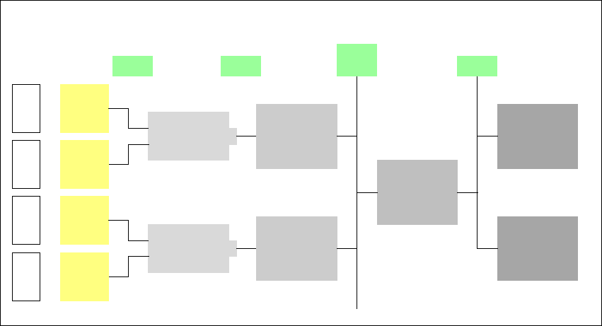
The PCB barcode reader is used to automatically record and decode barcodes on PCBs. The
PCB barcode reader sends the read data via its serial interface to the transport controller and then
for further processing to the machine controller via the CAN bus.
Fig. 7.5 - 1 PCB barcode block diagram
7
The PCB barcode readers are installed on the input side of the placement machine on the PCB
conveyor. Up to four devices can be retrofitted to each machine. The barcode readers are fitted
so that the barcode labels on the topside and underside of the PCBs can be scanned on both
tracks of the dual conveyor.
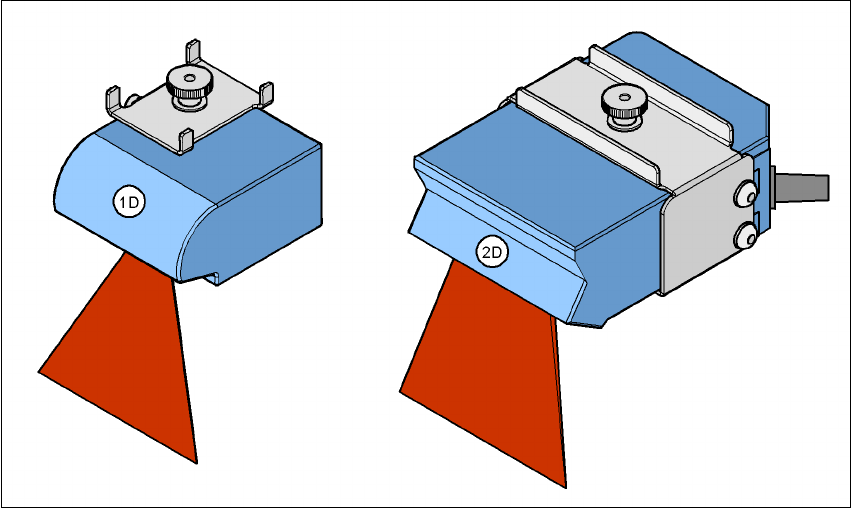
There are two variants of the barcode reader:
– 1D barcode reader
This barcode reader processes barcodes. 7
– 2D barcode reader
This barcode reader processes matrix code. Matrix code is primarily used when there is
not enough space for barcode labels. The 2D barcode reader also reads conventional bar-
codes. 7
Device number
1
Bar-
code
reader
Distribution
board
Transport
controller,
right
Barcode
reader
bottom
2
3
Bar-
code
reader
Distribution
board
Transport
controller,
left
Barcode
reader
bottom
4
Machine
controller
Station
computer
SIPLACE Pro
computer
LAN
CAN
bus
V-24V-24
User Manual SIPLACE HF Series 7 Station extensions
Software Version SR.505.xx 05/2004 US Edition 7.5 PCB barcode reader
309
7
Fig. 7.5 - 2 1D and 2D barcode readers
The PCB barcode readers are fixed to the top and bottom profiled rail using retainers. These can
be positioned as required on the profiled rails, and aligned with respect to the barcode labels. De-
pending on the position of the barcode strips, the barcode reader can be attached in a few simple
steps so that the strips can be read parallel to or across the PCB transport direction.
7.5.2 Description of the functions
The SIPLACE PCB barcode reader supports the flexible manufacture of SMD products, and in-
creases placement reliability. It recognizes all the code types conventionally used in industrial ap-
plications.
The laser scanner reads the barcode label on the topside or underside of each incoming PCB as
they are transported onto the input conveyor. The SIPLACE Pro computer uses the barcode in-
formation to automatically select the right placement program from the previously created barcode
assignment list (BA list), and sends it to the station. If a barcode filter is defined, only information
that is identified as relevant within the barcode is compared. This procedure is carried out time
neutrally during placement of the PCB already in the machine. If several PCBs with the same bar-
code enter in succession, the program is only transferred the first time. The following requirements
apply to all products to be produced using the PCB barcode:
– The component set-up must be identical on all the machines on the line
– All PCBs must be of the same width